background image

20036644

24 

GB

Installation

4.7.3

Accessibility to the interior of the combustion 
head

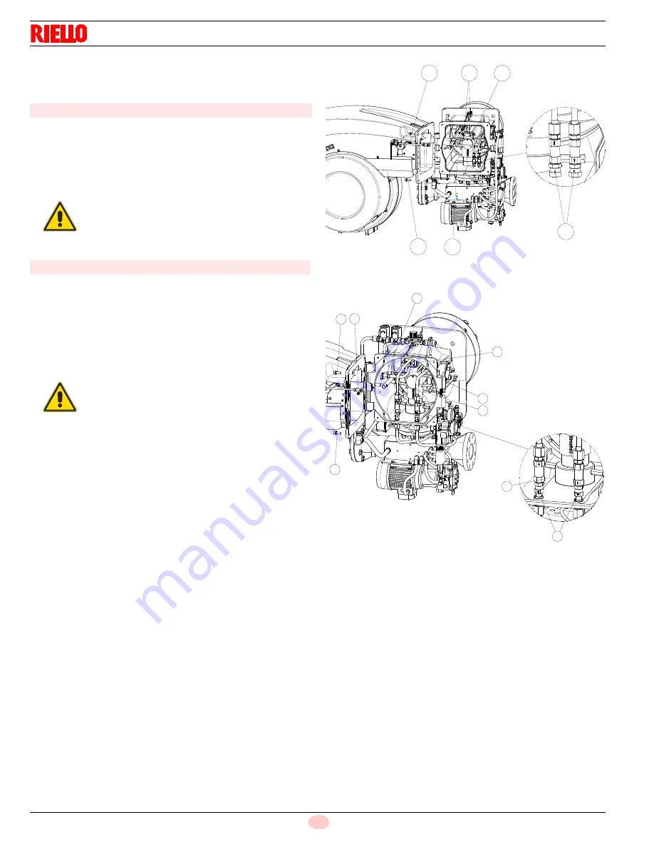
In order to reach inside the combustion head proceed as follows:

open burner at hinge (Fig. 14) after removing the 4 screws 1);

disconnect the wires 2) from the electrodes;

disconnect the oil pipes by unscrewing the two connectors 3);

unscrew the under part of the elbow 4) until it comes free of its
slot.

Extract the internal part  5) of the combustion head.

Disconnect the electrical wiring related to oil pump/servomo-
tor, air servomotor and gas pressure switch;

disconnect the leverages related to air damper and head
movement;

unscrew the 4 x fixing screws 1); 

release the cable of the electrode 2);

disconnect the oil pipes by unscrewing the two
connectors 3). 

Release the ignition pilot retainer;

remove the screw/gas pressure test point 6) of the combus-
tion head;

unscrew the under part of the elbow until it comes free of its
slot;

extract the internal part  5) of the combustion head.

RLS 300 - 400 - 500/E model (Fig. 14)

WARNING

While unscrewing, some fuel may leak out.

RLS 650 - 800/E model (Fig. 15)

WARNING

While unscrewing, some fuel may leak out.

Fig. 14

1

4

1

2

5

3

A

D3508

Fig. 15

1

2

2

3

4

7

5

8

6

D9424

Summary of Contents for RLS 300/E

Page 1: ...instructions Dual fuel light oil gas burners Progressive two stage or modulating operation CODE MODEL C9131000 C9131010 C9131001 RLS 300 E C9132010 C9132001 RLS 400 E C9133010 C9133001 RLS 500 E C9134010 C9134001 RLS 650 E C9135010 C9135001 RLS 800 E GB ...

Page 2: ......

Page 3: ... plants 14 3 9 Minimum furnace dimensions 15 3 10 Control box for the air fuel ratio LMV51 16 3 11 Actuators 21 4 Installation 22 4 1 Notes on safety for the installation 22 4 2 Handling 22 4 3 Preliminary checks 22 4 4 Operation position 22 4 5 Removal of the locking screws from the shutter 23 4 6 Boiler plate 23 4 7 Securing the burner to the boiler 23 4 7 1 Blast tube length 23 4 7 2 Burner sec...

Page 4: ...5 2 4 Fan air gate valve 39 5 3 Burner firing 39 5 4 Fuel change 39 5 5 Adjustments before first firing gas operation 40 5 6 Burner start up 40 5 6 1 Combustion air adjustment 41 5 6 2 Air adjustment for maximum output 41 5 6 3 Adjusting gas air delivery 41 5 6 4 Adjusting oil air delivery 41 5 6 5 Air fuel control and power modulation system 41 5 7 Final calibration of the pressure switches 42 5 ...

Page 5: ... generator is to be installed The instruction manual shows the serial number of the burner the address and telephone number of the nearest Assis tance Centre The system supplier carefully informs the user about the use of the system any further tests that may be necessary before the system is started up maintenance and the need to have the system checked at least once a year by the manufacturer or...

Page 6: ...is manual 1 2 1 Owner s responsibility Please pay attention to the Safety Warnings contained within this instruction manual Keep this manual for your records and provide it to your quali fi ed service agency for use in profession ally setting up and maintaining your burner Your burner will provide years of ef fi cient operation if it is pro fessionally installed and maintained by a qualifi ed serv...

Page 7: ...ith the burner components is not allowed apart from the parts requiring maintenance Only those parts envisaged by the manufacturer can be replaced 2 2 Personnel training The user is the person body or company that has acquired the machine and intends to use it for the specific purpose He is re sponsible for the machine and for the training of the people working around it The user Undertakes to ent...

Page 8: ...delivery Gas pressure at maximum delivery 2 SCFH WC 14 390 9 0 17 042 13 0 19 692 15 0 Operation Low high or modulating Nozzle number 1 Standard applications Boilers water steam thermal oil Ambient temperature F 32 104 0 40 C Combustion air temperature F max 140 60 C Pump delivery at 300 PSI pressure range fuel temperature GPH PSI F max 218 102 580 302 150 C 218 102 580 302 150 C 290 102 580 302 1...

Page 9: ...cal power consumption W 8450 8450 9300 Electrical control circuit consumption W max 750 Total electrical consumption W 9200 9200 10050 Electrical protection NEMA 1 Model RLS 400 E RLS 500 E RLS 650 E RLS 800 E RBNA Code C9132010 C9133010 C9134010 C9135010 Control circuit power supply V Ph Hz 120 1 60 Main power supply 10 V Ph Hz 460 3 60 Fan motor rpm HP V A 3460 10 460 14 9 3500 20 460 30 5 3640 ...

Page 10: ... 8200 Electrical control circuit consumption W max 750 Total electrical consumption W 8950 Electrical protection NEMA 1 Model RLS 400 E RLS 500 E RBNA Code C9132010 C9132001 C9133010 C9133001 Control circuit power supply V Ph Hz 120 1 60 Main power supply 10 V Ph Hz 460 3 60 575 3 60 460 3 60 575 3 60 Fan motor rpm HP V A 3510 10 460 11 5 3510 10 575 8 8 3545 20 460 23 5 3545 20 575 18 8 Pump moto...

Page 11: ...mer Oil V1 V2 I1 I2 120 V 2 x 5 kV 2 7 A 30 mA Gas V1 V2 I1 I2 120 V 1 x 8 kV 1 6 A 20 mA Electrical power consumption W 21850 21850 25750 25800 Electrical control circuit consumption W max 750 Total electrical consumption W 22600 22600 26500 26550 Electrical protection NEMA 1 Model Code Code RBNA Voltage Fan motor starting Flame safeguard RLS 300 E 20041484 C9131000 208 220 3 60 Direct Burner mou...

Page 12: ...lange to the boiler No 4 Spacers No 2 Instruction booklet No 1 A B I D E F C G H R L S S R Fig 2 D3505 inch A B C D E F G H I L R S RLS 300 E 52 3 16 20 1 2 6 7 16 12 5 16 23 5 32 ANSI 3 31 5 32 34 9 64 14 1 32 46 1 4 41 17 32 12 19 32 RLS 400 E 52 3 16 20 1 2 6 7 16 12 5 16 23 5 32 ANSI 3 30 1 2 34 9 64 14 1 32 46 1 4 41 17 32 12 19 32 RLS 500 E 52 3 16 20 1 2 6 7 16 14 17 32 23 5 32 ANSI 3 30 1 ...

Page 13: ... type 19 Air pressure test point 20 Max gas pressure switch with pressure test point 21 QRI flame detector 22 Air pressure test point 23 Oil modulator and gas butterfly valve servomotor 24 Pump 25 Pump motor 26 Min oil pressure switch 27 Oil shutoff VOG valve 28 Nozzle delivery pressure gauge 29 Nozzle return pressure gauge 30 Oil modulator 31 Strainer 32 Check valve 33 Air pressure test point 1 5...

Page 14: ...tional actuator or O2 control 28 KO relay 29 KG1 relay 30 DIN bar for X2 terminal strip thermal relays and contactors 31 Star delta starter timer only for star delta version 32 Holes for cables grommets for electrical wirings accessories and power supply to be carried out by the installer 33 Plug socket for maximum pressure switch 34 Plug socket for air actuator 35 Plug socket for QRI flame sensor...

Page 15: ...6 8 10 12 14 16 18 20 m b a r 22 9 8 7 6 5 4 3 2 0 1 w c 0 5600 5200 4800 4400 4000 3600 3200 2800 2400 2000 1600 1200 800 400 0 6000 9200 8800 8400 8000 7600 7200 6800 6400 M Btu h kW 2000 4000 6000 8000 10000 12000 14000 16000 18000 20000 22000 24000 26000 28000 30000 Fig 5 D11255 RLS 650 E RLS 800 E 0 2 4 6 8 10 12 14 16 18 20 m b a r 8 7 6 5 4 3 2 0 1 w c 0 5600 5200 4800 4400 4000 3600 3200 2...

Page 16: ... Capacity m a s l 0 100 305 610 915 1220 1525 1830 2135 2440 ft a s l 0 328 1000 2000 3000 4000 5000 6000 7000 8000 500 494 500 512 530 551 571 593 616 641 669 1000 987 1000 1023 1061 1101 1142 1186 1232 1282 1337 1500 1481 1500 1535 1591 1652 1713 1778 1848 1924 2006 2000 1974 2000 2046 2121 2202 2284 2371 2464 2565 2675 2500 2468 2500 2558 2652 2753 2855 2964 3079 3206 3343 3000 2962 3000 3069 3...

Page 17: ... 4 57 4 74 4 93 5 13 5 35 4 50 4 44 4 50 4 60 4 77 4 95 5 14 5 33 5 54 5 77 6 02 5 00 4 94 5 00 5 12 5 30 5 51 5 71 5 93 6 16 6 41 6 69 5 50 5 43 5 50 5 63 5 83 6 06 6 28 6 52 6 77 7 05 7 35 6 00 5 92 6 00 6 14 6 36 6 61 6 85 7 11 7 39 7 69 8 02 6 50 6 42 6 50 6 65 6 89 7 16 7 42 7 71 8 01 8 34 8 69 7 00 6 91 7 00 7 16 7 42 7 71 7 99 8 30 8 62 8 98 9 36 7 50 7 40 7 50 7 67 7 96 8 26 8 56 8 89 9 24...

Page 18: ...ust also be observed Condensation and ingress of humidity must be avoided Should such conditions occur make sure that the unit will be completely dry before switching on again Static charges must be avoided since they can damage the unit s electronic components when touched Mechanical design The LMV5 is a microprocessor based burner management sys tem with matching system components for the contro...

Page 19: ...use externally Max 16 AT Undervoltage Safety shutdown from operating position at mains voltage Restart on rise in mains voltage AC 96 V AC 100 V Oil pump magnetic clutch nominal voltage Nominal current Power factor 1 6A cos 0 4 Air pressure switch test valve nominal voltage Nominal current Power factor 0 5A cos 0 4 Terminal loading Outputs Total contact loading Mains voltage Input current of unit ...

Page 20: ...V Fuel valve V1 Fuel valve V2 Fuel valve V1 Fuel valve V2 Fuel valve V3 Fuel valve SV Oil INPUTS Timer 1 Timer 2 Fuel 1 oil Fuel 2 gas Controller ON internal external Air pressure switch LP Start release oil Fuel selection Fan conductor contact GSK Interval 1 ti1 Operation 2 LK K POS SR ON Pressure test Direct start Air Aux VSD Actuator 1 4 5 CPI function with LMV52 alternative start signal Fig 8 ...

Page 21: ...n1 t78 Postpurge time 3 gas oil tn3 t80 Valve proving evacuate time t81 Leakage test time atmospheric pressure t82 Leakage test filling test t83 Leakage test time gas pressure tmn1 Min time extraneous light test 5 s after skip over of prepurge tmx1 Max damper running time tmx2 Max time startup release tmx3 Max time circulation heavy oil tn Postpurge time TSA1 Safety time 1 TSA2 Safety time 2 tv Pr...

Page 22: ... Output is active when fan is on and for another 15 s after fan is switched off 17 Parameter Start pressure switch valve PS_Re li_Inv Output pressure switch valve will be logically inverted 18 Parameter Alarm act deact deactivated The alarm output can temporarily be deactivated for cur rent error only 19 Parameter Only with LMV52 Continuous pilot gas oil Activated Pilot valve is also activated in ...

Page 23: ...230 V section of the actuator is strictly segregat ed from the functional low voltage section The holding torque is reduced when the actuator s power supply is switched off Technical data WARNING To avoid injury to persons damage to property or the environment the following warning notes should be observed Do not open interfere with or modify the actua tors WARNING The housing cover may only be re...

Page 24: ...ce WARNING The handling operations for the burner can be high ly dangerous if not carried out with the greatest at tention keep any unauthorised people at a distance check the integrity and suitableness of the available means of handling Check also that the area in which you are working is empty and that there is an adequate escape area i e a free safe area to which you can quickly move if the bur...

Page 25: ...ring Create a suitable hoisting system by hooking onto the rings 4 removing the fastening screws 1 securing the cover 2 first Slip the thermal protection onto the blast tube 3 Place entire burner on the boiler hole arranged previously see Fig 12 and fasten with the screws given as standard equipment The coupling of the burner boiler must be airtight WARNING Remove the screws and the nuts 1 2 Fig 1...

Page 26: ...pump servomo tor air servomotor and gas pressure switch disconnect the leverages related to air damper and head movement unscrew the 4 x fixing screws 1 release the cable of the electrode 2 disconnect the oil pipes by unscrewing the two connectors 3 Release the ignition pilot retainer remove the screw gas pressure test point 6 of the combus tion head unscrew the under part of the elbow until it co...

Page 27: ... 8 Electrode and ignition pilot adjustment Place the electrode and the ignition pilot observing the dimensions in Fig 16 and Fig 17 RLS 300 400 500 E model Fig 16 27 32 5 8 Fig 16 D11260 RLS 650 800 E model Fig 17 5 8 Fig 17 D11256 ...

Page 28: ...ate Supply pressure kg h Code PSI kg h GPH PSI GPH PSI X 130 3045477 270 105 0 33 6 100 8 3 300 X 150 3045479 264 125 0 40 0 100 11 8 300 X X 175 3045481 258 149 4 47 8 100 13 8 300 X X 175 3045481 260 156 3 50 0 100 13 8 300 X X 200 3045483 267 187 5 60 0 100 15 0 300 X X X 250 3045487 260 211 3 67 6 100 16 6 300 X X X 250 3045487 262 218 8 70 0 100 16 6 300 X X X 275 3045489 268 250 0 80 0 100 1...

Page 29: ...e fitted on the nozzle holder To set the delivery range within which the nozzle must work nozzle return line fuel pressure must be adjusted according to Tab G WARNING Do not use any sealing products such as gas kets sealing compound or tape Be careful to avoid damaging the nozzle seal ing seat The nozzles must be screwed into place tightly but not to the maximum torque value provided by the wrench...

Page 30: ...etting to that illustrated in diagram Fig 21 do this by moving the tie rod onto the next highest index thus increasing the combustion head s opening and hence air delivery If combustion requirements require you to move spacer 1 Fig 20 onto the 1st or 2nd hole of the gear and at the same time the hinge is on the right you need to fit the spacers 4 Fig 20 supplied with the burner Proceed as follows ...

Page 31: ... head assembly unscrew the screws and remove the 8 tangential tubes 1 unscrew the 4 screws and disassemble the diffuser disc 2 unscrew and remove the 6 nozzles 3 Re assemble with reverse procedure re placing all the burner components as originally Only for RLS 400 E model WARNING To achieve operation at minimum output the com bustion head s gas pipes must be adjusted to hole position 5 Fig 22 Fig ...

Page 32: ...e fails to prime or stops priming 4 11 2 The loop circuit A loop circuit consists of a loop of piping departing from and return ing to the tank with an auxiliary pump that circulates the fuel under pressure A branch connection from the loop goes to feed the burner This circuit is extremely useful whenever the burner pump does not succeed in self priming because the tank distance and or height diff...

Page 33: ... variation of a section by rotating the servomotor 23 Fig 3 on page 11 which simultaneously also controls the gas butterfly valve Pressure governor at 0 maximum opening minimum pres sure on nozzle return Pressure governor at 90 minimum opening maximum pres sure on nozzle return The servomotor is operated by the electronic cam 11 Fig 4 on page 12 by means of this device it is possible to set differ...

Page 34: ...s Pump model TA3 RLS 300 400 E TA4 RLS 500 E TA5 RLS 650 800 E Min delivery rate at 300 PSI pressure GPH 218 290 403 Delivery pressure range PSI 102 580 102 435 Max suction pressure PSI 7 0 Viscosity range cSt 3 75 Max oil temperature F 302 150 C Max return pressure PSI 73 0 Pressure calibration in the factory PSI 300 Fig 26 2 5 6 1 4 3 5 D12112 WARNING Before starting the burner make sure that th...

Page 35: ... type approved according to required standards and is supplied separately from the burner Fig 28 Key Fig 28 1 Gas input pipe for main burner 2 Manual valve 3 Min gas pressure switch 4 Safety shut off valve 5 NO vent valve 6 Regulating shut off valve 7 Gas input pipe for pilot 8 Gas adjustment butterfly valve 9 Burner 10 Max gas pressure switch 11 Manual valve for seal control 12 Pilot regulator WA...

Page 36: ...or RLS 500 E Maximum output operation Gas pressure at test point 1 Fig 29 11 7 WC Pressure in combustion chamber 2 WC 11 7 2 9 7 WC An output of 15148 MBtu hr shown in Tab J corresponds to 9 7 WC pressure column 1 This value serves as a rough guide the effective delivery must be measured at the gas meter Note See the accompanying instructions for the adjustment of the gas train Tab J 1 2 Fig 29 S8...

Page 37: ...t from those shown in the electri cal layouts Check that the electrical supply of the burner corresponds to that shown on the identification label and in this manual Do not invert the neutral with the phase in the electrical supply line Any inversion would cause a lockout due to firing failure The electrical safety of the device is obtained only when it is correctly connected to an efficient earth...

Page 38: ...e motor is 400V To reset in the case of an intervention of the thermal relay press the button RESET Fig 31 The button STOP Fig 31 opens the NC 95 96 contact and stops the motor To test the thermal relay insert a screwdriver in the window TEST Fig 32 and move it in the sense of the arrow towards right 4 16 2 Electronic thermal relay To reset in the case of an intervention of the thermal relay press...

Page 39: ...t 575V only for RLS 300 E WARNING the motors manufactured for 575V IE2 Epact voltage have the same control box base of the IE1 motors Please pay attention to the indications in case of maintenance or substitution 4 19 Reversible direction WARNING If it is necessary to reverse the direction then reverse the two main supply phases For example L1 with L2 there is not difference between IE1 and IE2 Ep...

Page 40: ...n at 575V only for RLS 400 500 650 800 E WARNING the motors manufactured for 575V IE2 Epact voltage have the same control box base of the IE1 motors Please pay attention to the indications in case of maintenance or substitution 4 22 Reversible direction WARNING If it is necessary to reverse the direction then reverse the two main supply phases For example L1 with L2 there is not difference between...

Page 41: ...nts at page 41 5 3 Burner firing Having completed the checks indicated in the previous heading the ignition pilot of the burner should fire Set switch 1 Fig 42 to LOCAL Set switch 2 Fig 42 to GAS If the motor starts but the flame does not appear and the flame safeguard goes into lock out reset and wait for a new firing at tempt Pilot adjustment has been illustrated on page 25 Having adjusted the p...

Page 42: ... switch to position OIL for oil operation and GAS for gas operation Fig 44 NOTE for further information please refer to the specific instruction of the control box CAUTION Before starting up the burner it is good practice to adjust the gas train so that ignition takes place in conditions of maximum safety i e with gas delivery at the minimum D3515 Fig 43 DANGER Make sure that the lamps or testers ...

Page 43: ...omplete the procedure slowly synchronizing the combustion with the two servomotors Store the different setting points 5 6 5 Air fuel control and power modulation system The air fuel and power modulation system installed on RLS burner series provides a set of integrated functions ensuring top level energy and operational performance from the burner both for single and grouped burners e g boiler wit...

Page 44: ...um gas pressure switch Fig 47 after having per formed all other burner adjustments with the maximum gas pres sure switch set to the end of the scale With the burner operating at MAX output reduce the adjustment pressure by slowly turning the adjustment dial anticlockwise until the burner locks out Then turn the dial clockwise by 0 8 WC and repeat burner firing If the burner locks out again turn th...

Page 45: ... switch The low oil pressure switch Fig 49 is factory set to 261 PSI 18 bar If the oil pressure goes down this value in the delivery piping the pressure switch stops the burner Burner starts again automatically if the pressure goes above 261 PSI 18 bar after burner start up Fig 49 D10627 ...

Page 46: ... the load control is consequently closed the burner progressively increases out put up to MAX If subsequently the temperature or pressure increases until the load control opens the burner progressively decreases output down to MIN The burner shuts off when demand for heat is less than the heat supplied by the burner in the MIN output The servomotor returns to the 0 angle The air damper closes comp...

Page 47: ...he maximum end of scale position Rotate the maximum oil pressure switch at the minimum of the scale The burner must stop in lockout Switch off the burner and disconnect the voltage Disconnect the minimum gas pressure switch Rotate the minimum low oil pressure switch at the maximum of the scale The burner must not start Cover the QRI flame detector The burner must stop in lockout due to firing fail...

Page 48: ...ill cause a reduction in the air flow rate and provoke polluting combustion Burner Clean the outside of the burner Clean and grease the cam variable profile Boiler Clean the boiler as indicated in its accompanying instructions in or der to maintain all the original combustion characteristics intact es pecially the flue gas temperature and combustion chamber pressure Pump Delivery pressure must cor...

Page 49: ...tion In case the combustion values found at the beginning of the inter vention do not respect the standards in force or in any case do not correspond to a proper combustion contact the Technical Assis tant and have him carry out the necessary adjustments 6 3 Opening the burner Remove the tie rod 1 Fig 51 of the head movement lever loosening nut 2 Disconnect the gas servomotor test point 3 Disconne...

Page 50: ...20036644 48 GB Appendix Spare parts A Appendix Spare parts ...

Page 51: ...6 3013945 ELBOW 6 3014118 ELBOW 7 3014117 CONTROL WHEEL 7 3014116 CONTROL WHEEL 8 3013451 SERVOMOTOR B 9 20027917 THERMAL RELAY 230V 460V 575V C 10 20027247 CONTACTOR 11 3013326 AIR INTAKE ASSEMBLY 11 3013961 AIR INTAKE ASSEMBLY 12 20006192 FAN C 12 20006205 FAN C 12 3013317 FAN C 12 20041011 FAN C 12 20037158 FAN C 13 20008598 MOTOR 7 5HP 230V 460V C 13 3014152 MOTOR 7 5HP 575V C 13 20013155 MOTO...

Page 52: ... C 30 20041804 SHUTTER C 30 20038374 SHUTTER C 30 20011089 SHUTTER C 31 3013314 END CONE B 31 3013642 END CONE B 31 20026702 END CONE B 31 3013957 END CONE B 32 3013328 GASKET 32 20011117 GASKET 32 3013956 GASKET 33 3012956 TRANSFORMER 34 20031413 HORN 35 3012948 AIR PRESSURE SWITCH A 35 20013975 AIR PRESSURE SWITCH A 36 3013363 CONNECTOR C 37 3013284 TRANSFORMER 38 20010969 RELAY C 39 3012841 BAS...

Page 53: ... 58 3013960 HINGE 59 3013549 SPRAY NOZZLE 59 3014228R SPRAY NOZZLE 59 20011191 SPRAY NOZZLE 60 20041674 SHUTTER 60 20042719 SHUTTER 60 20011151 SHUTTER 61 3007079 SEAL B 61 3007166 SEAL B 62 3013460 CONNECTOR C 62 20011120 CONNECTOR C 63 3013553 TUBE 63 3014202 TUBE 63 20011196 TUBE 64 3013554 TUBE 64 3014203 TUBE 64 20011197 TUBE 65 3012549 CONNECTOR C 65 20011192 CONNECTOR C 66 3013461 VALVE NOT...

Page 54: ...TUBE 78 20029212 VALVE 79 20029248 VALVE 80 20042849 TUBE 81 20042850 TUBE 82 20029233 FILTER 83 3020068 RELAY 84 3020071 BASE 85 20043289 BASE 86 20028312 OVERLOAD 230V 460V 86 20043275 OVERLOAD 460V 575V 87 20030705 CONTACTOR 88 20014366 FUSE HOLDER A 89 20043271 CONNECTOR 90 20043328 RELAY SUPPORT 91 20043307 RELAY SUPPORT 92 20043329 TIMER 93 20013967 AUXILIARY CONTACT 94 20013973 CONTACTOR 95...

Page 55: ...essories 53 20036644 GB Gas train according to UL Standards B Appendix Accessories WARNING The installer is responsible for the supply and instal lation of any required safety device s not indicated in this manual ...

Page 56: ...ncy Low Fire High Fire Low Fire Flame Signal Overfire Draft High Fire Flame Signal OIL OPERATION Oil supply pressure CO2 Low Fire High Fire Oil suction pressure O2 Low Fire High Fire Control Power Supply CO Low Fire High Fire Burner Firing Rate NOX Low Fire High Fire Low Fire Flame Signal Net Stack Temp Low Fire High Fire High Fire Flame Signal Comb Efficiency Low Fire High Fire Low Fire Nozzle Si...

Page 57: ......

Page 58: ......

Page 59: ......

Page 60: ...Pond Park Road 1 800 4 RIELLO 2165 Meadowpine Blvd Hingham Massachusetts 1 800 474 3556 Mississauga Ontario U S A 02043 Canada L5N 6H6 http www riello burners com RIELLO S p A I 37045 Legnago VR Tel 39 0442 630111 http www riello it http www rielloburners com ...

Reviews: