11
20034293
GB
Technical description of the burner
4.7
Overall dimensions
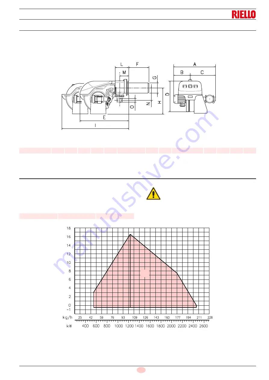
The maximum dimensions of the burner are given in Fig. 2.
Bear in mind that inspection of the combustion head requires the
burner to be opened and the rear part withdrawn on the slide
bars.
The maximum dimension of the burnerwhen open, without cas-
ing, is give in measurement I.
Tab. G
(1)
Blast tube: short-long
4.8
Firing rate
During operation, burner output varies between:
•
a
MAXIMUM OUTPUT
, selected within area A,
•
and a
MINIMUM OUTPUT
, which must not be lower than the
minimum limit in the diagram.
Fig. 2
D3169
mm
A
B
C
D
E
F
(1)
G
H
I
(1)
L
M
N
O
RLS 250/M MZ
904
427
477
555
863
412-542
222
435
1442-1587
237
141
186
Rp2
Model
kW
kg/h
RLS 250/M MZ
550
46
WARNING
The firing rate value (Fig. 3) has been obtained
considering an ambient temperature of 20 °C, an
atmospheric pressure of 1013 mbar (approx. 0 m
above sea level), and with the combustion head
adjusted as shown on pag. 27.
Fig. 3
Pr
essure in combustion
ch
am
be
r -
mbar
D8855
A
Thermal power
Summary of Contents for RLS 250/M
Page 2: ...Original instructions ...
Page 45: ...43 20034293 GB Appendix Electrical panel layout ...
Page 46: ...20034293 44 GB Appendix Electrical panel layout ...
Page 47: ...45 20034293 GB Appendix Electrical panel layout ...
Page 48: ...20034293 46 GB Appendix Electrical panel layout ...
Page 49: ...47 20034293 GB Appendix Electrical panel layout ...
Page 51: ......


