background image

3445

6

The intake-tube / burner system must not allow a loss of over 2 m

3

/h at 0.5mbar:

for instance, the above requirements will be met if you use flues for pressure exhaust of flue gases (the con-
densation kind).

Make sure the air intake tube’s inlet is positioned so that it is not likely to be obstructed by foreign matter and,

where necessary, use suitable screens.

The temperature of the incoming air must not exceed 40 °C;

The inside diameter of the hose must be at least 80 mm.

The intake tube can be up to 6 metres in length.

Warning: length is reduced if there are bends in the intake section.
For instance, using a tube with a smooth inside surface, you must allow for the following losses:
- for each 45° bend, tube length is reduced by 0.5 m;
- for each 90° bend, tube length is reduced by 0.8 m.

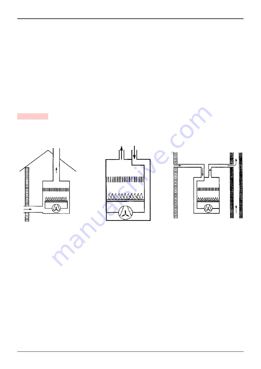
BURNER  INSTALLATION  MUST  COMPLY  WITH  ONE  OF  THE  INSTALLATIONS  ILLUSTRATED  IN  THE
FIGURES BELOW.

Under no circumstances should the air’s entry in the hose intake area be obstructed.

The hose must not be blocked in any way or feature a shutting device (valves, membranes etc.).

Coaxial tubes must not be installed for any reason.    

ATTENTION

S7851

S7853

S7876

Summary of Contents for RC2-38

Page 1: ...2903445 2 05 2017 Installation use and maintenance instructions Light oil burners One stage operation CODE MODEL TYPE 3571000 RC2 38 732T3 3572080 RC2 1 46 732T6 20062926 RC2 1 46 TL 732T6...

Page 2: ......

Page 3: ...zzles recommended 10 4 3 Pump pressure 10 4 4 Maintenance position 11 4 5 Electrodes adjustment 11 4 6 Air adjustment 12 4 7 Burner start up cycle 12 5 MAINTENANCE 13 5 1 Access to the fan 13 6 FAULTS...

Page 4: ...l supply Single phase 50Hz 230V 10 Motor Run current 0 75A 2800 rpm 294 rad s Capacitor 4 5 F Ignition transformer Secondary 8 kV 16 mA Pump Pressure 7 15 bar Absorbed electrical power 0 115 kW BURNER...

Page 5: ...e 3 horizontally against the feeder 5 making sure you pull the locking device 6 fig 5 page 4 turn clockwise to fasten the air intake 3 to the burner and release the locking device 6 The air intake can...

Page 6: ...eans of the two screws 11 screwing it on with a driving torque of 0 8 Nm follow the above procedure in the reverse order restoring the feeder 5 to its original position tightening the two screws 9 wit...

Page 7: ...In the case of BF application combustion air is fed through a flexible or rigid pipe connected to the air intake B FOR CORRECT BF APPLICATION THE BURNER MUST BE INSTALLED ON AN APPROPRIATE BF BOILER C...

Page 8: ...st 80 mm The intake tube can be up to 6 metres in length Warning length is reduced if there are bends in the intake section For instance using a tube with a smooth inside surface you must allow for th...

Page 9: ...the burner or the fuel pump ing systems are on the outside of the boiler Figure 12 is an example of connection to a pressurised ring no mat ter what position the ring feeder tank is in In the system...

Page 10: ...tion line In this case a non return valve is not required Should however the return line arrive over the fuel level a non return valve is required This solution however is less safe than previous one...

Page 11: ...ation The electrical wiring carried out by the installer must be in compliance with the rules in force in the Country WARNING DO NOT EXCHANGE NEUTRAL WITH PHASE ACCESS TO THE FLAME SENSOR see fig 16 T...

Page 12: ...outside air temperature 20 C adjust CO2 to 12 0 2 4 2 NOZZLES RECOMMENDED Delavan type W Hago type SS Steinen type Q Danfoss type S Angle 60 In most cases 80 In case of flame detachment during igniti...

Page 13: ...7 Refit following the above procedure in the reverse order 4 5 ELECTRODES ADJUSTMENT To reach the electrodes proceed as described in chapter 4 4 MAINTENANCE POSITION Electrode position is not adjustab...

Page 14: ...s when turned anticlockwise Adjustments in the table on page 10 are given as an approximate guide only Each system features operating conditions that cannot be known in advance actual nozzle delivery...

Page 15: ...ad in the fuel exit area Leave the burner working without interruptions for 10 min and set rightly all the components stated in this manual Then carry out a combustion check verifying Smoke temperatur...

Page 16: ...istance The red led on the command and control equipment is off check the resistance and replace if necessary The burner stays in pre purging The flame sensor perceives external light Eliminate the so...

Page 17: ...nt maintenance or improper use 7 1 BURNER IDENTIFICATION The Identification Plate on the product gives the serial number model and main technical and performance data If the Identification Plate is ta...

Page 18: ......

Page 19: ......

Page 20: ...Subject to modifications RIELLO S p A I 37045 Legnago VR Tel 39 0442 630111 http www riello it http www riello com...

Reviews: