E
XTERNAL PROTECTION DEVICES
CIRCUIT BREAKER
When setting up the power supply line, install a circuit breaker with trip curve C (or D depending on the type of load) upstream
from the UPS, as indicated in the following table:
Automatic external protection devices*
UPS model
Mains input
Separate bypass input (optional)
30kVA
63A
63A
40kVA
80A
80A
* In the case of a non-linear load, oversize the neutral line N correctly after site assessment.
If the protection device upstream of the UPS interrupts the neutral conductor, it must also interrupt all the phase
conductors at the same time (quadripolar switch).
Output protections (recommended selectivity values)
Normal fuses (gL-gG)
In (Nominal current)/7
Magnetothermal switches (C curve)
In (Nominal current)/7
Ultrarapid fuses (GF)
In (Nominal current)/3
DIFFERENTIAL
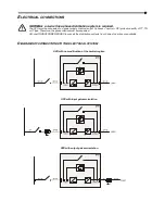
In the absence of an input separating transformer, the neutral from the mains power supply is connected to the neutral of the
UPS output. This way the neutral regime of the equipment is not modified.
THE INPUT NEUTRAL IS CONNECTED TO THE OUTPUT NEUTRAL
THE DISTRIBUTION SYSTEM THAT POWERS THE UPS IS NOT MODIFIED BY THE UPS
WARNING: make sure that the equipment is connected correctly to the input neutral, or else
damages to the UPS may be caused.
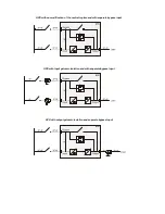
The neutral regime is modified only in presence of an isolation transformer or when the UPS operates with a neutral
isolated upstream.
When operating from mains power, a differential switch located at the input can intervene as the output circuit is not isolated
from the input circuit. Anyhow, other differential switches can be inserted at the output, possibly coordinated with the switches at
the input.
The differential switch located upstream must have the following features:
Differential current adjusted to the sum of the UPS load. It is strongly recommended to keep an adequate margin in
order to avoid delayed interventions (100mA min. - 300mA recommended)
type B or type A
delay greater than or equal to 0,1s

