background image

20144819

16 

GB

Installation

5.7

Combustion head adjustment

The  adjustment  of  the  combustion  head  depends  only  on  the
maximum output developed by the burner.
Therefore, this value must be set before adjusting the combus-
tion head.
Two adjustments of the head are envisaged:
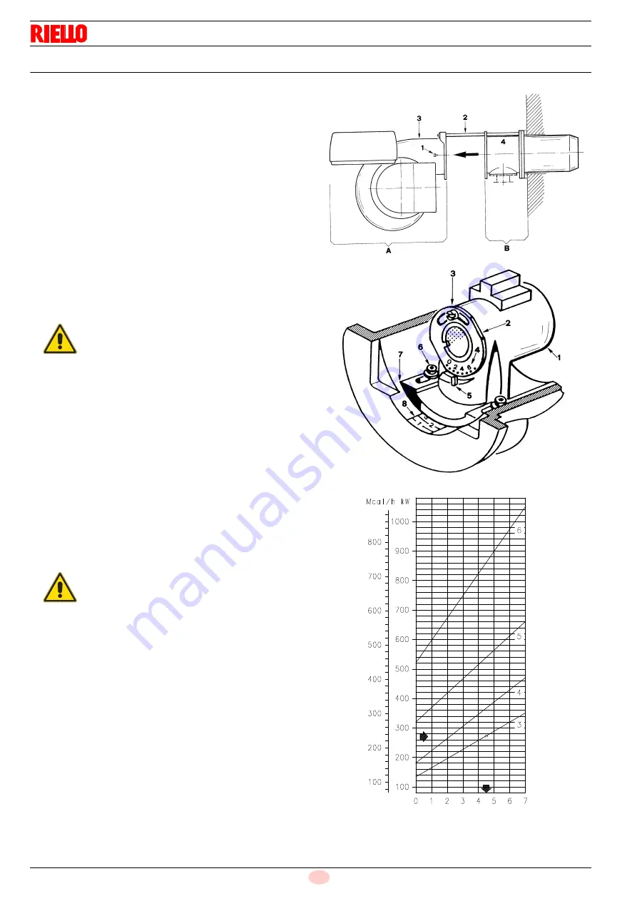
for the gas and for the air. They are carried out with the burner
open (Fig. 11), when the burner is fixed to the boiler.

Gas adjustment 

Loosen the screw 3)(Fig. 12).

Turn  the  ring  nut  2)  so  that  the  index  5)  lines  up  with  the
desired notch 4).

Tighten the screw 3) fully down.

Air adjustment 

Loosen the two screws 6)(Fig. 12).

Move the elbow 1) forward or backward so that its rear sur-
face 7) lines up with the desired notch of the label 8).

Lock the screws 6).

Example:

The GAS 3 burner is installed in a 240 kW boiler. Considering an
efficiency of 89%, the burner should deliver about 270 kW.
The diagram (Fig. 13) shows that the gas and air adjustments for
this burner output are carried out on notch 4.5.

NOTE:
The diagram shows the ideal adjustment of the head. If the
pressure in the gas supply network is low and does not allow
the desired pressure (and therefore output) to be reached, it
is  possible  to  further  open  the  ring  nut  2)(Fig.  12
)  by  1-2
notches. See also the note on page 18.

Finally close the burner:
-

Slide unit A on the two slide bars 2)(Fig. 11).

-

Put back the screws 1).

WARNING

The notch number for gas and air is the same and
is gained from the diagram (Fig. 13) in accordance
with the burner output.

WARNING

When the burner is closing on the two slide bars,
the  high  voltage  cable  and  the  flame  detection
probe cable should be pulled outwards until they
are slightly taut.

 Fig. 11

D202

 Fig. 12

D118

 Fig. 13

D227

GAS

Notches on the ring nut 2)(Fig. 12)
and on the label 8)(Fig. 12)

Summary of Contents for GAS 3

Page 1: ...ation use and maintenance instructions 20144819 3 01 2019 Forced draught gas burners One stage operation CODE MODEL TYPE 3751918 GAS 3 519 T1 3751617 GAS 4 516 T1 3751717 GAS 5 517 T1 3751817 GAS 6 51...

Page 2: ...Translation of the original instructions...

Page 3: ...n 13 5 1 Notes on safety for the installation 13 5 2 Handling 13 5 3 Preliminary checks 13 5 4 Operating position 14 5 5 Preparing the boiler 14 5 5 1 Boring the boiler plate 14 5 5 2 Blast tube lengt...

Page 4: ...eset 26 6 8 3 Visual diagnostics 26 6 8 4 Software diagnostics 26 7 Maintenance 27 7 1 Notes on safety for the maintenance 27 7 2 Maintenance programme 27 7 2 1 Maintenance frequency 27 7 2 2 Safety t...

Page 5: ...ds EN 676 EN 12100 and according to the European Directives GAR 2016 426 EU only 519 T1 Gas Devices Directive MD 2006 42 EC Machine Directive LVD 2014 35 EU Low Voltage Directive EMC 2014 30 EU Electr...

Page 6: ...ed out correctly may cause damage to the ma chine and or injury to people DANGER DANGER LIVE COMPONENTS This symbol indicates operations which if not car ried out correctly lead to electric shocks wit...

Page 7: ...of damage to things or injury to people if such damage injury was due to any of the following causes incorrect installation start up use and maintenance of the burner improper incorrect or unreasonab...

Page 8: ...ose parts envisaged by the manufacturer can be replaced 3 2 Personnel training The user is the person body or company that has acquired the machine and intends to use it for the specific purpose He is...

Page 9: ...230 50 Direct 3751617 GAS 5 TC 3 230 400 50 Direct 3751717 GAS 6 TC 3 230 400 50 Direct 3751817 Country of destination Gas category SE FI AT GR DK ES GB IT IE PT IS CH NO I2H DE I2ELL NL I2L I2E I2 43...

Page 10: ...arts list No 1 MODEL GAS 3 GAS 4 GAS 5 GAS 6 Type 519 T1 516 T1 517 T1 518 T1 Electrical supply 1 PH 1N 230V 50 Hz Electrical supply 3 PH 3 230 400V 10 50 Hz Electrical motor rpm kW V A 2750 0 250 230...

Page 11: ...amber 0 7 mbar the maximum pressure curve in comb chamber If the burner develops an output of 240 kW at a pressure in com bustion chamber of 5 mbar the work point is found on the maxi mum pressure cur...

Page 12: ...set in relation to special test boilers accord ing to EN 676 regulations In Fig 3 you can see the diameter and length of the test combus tion chamber Example Output 1500 Mcal h diameter 80 cm length...

Page 13: ...S 3 4 models 6 Motor contactor and thermal relay in GAS 5 6 models 7 Terminal board 8 Cable grommets for electrical wiring to be carried out by the installer 9 Control box with lockout pilot light and...

Page 14: ...the development of conden sate and humidity Otherwise before switching on again make sure that the entire control box is perfectly dry Static charges must be avoided since they can damage the control...

Page 15: ...be free from hazardous mixes e g chloride fluoride halo gen if present it is highly recommended to carry out cleaning and maintenance more frequently WARNING The handling operations for the burner can...

Page 16: ...on device in refractory material 7 must be in serted between the boiler refractory 8 and the blast tube 6 This protective fettling must not compromise the extraction of the blast tube WARNING The burn...

Page 17: ...e them Finally put back the fan 4 Fig 9 on the slide bars 3 put back the screws 2 and with the burner open proceed to the adjustment of the combustion head 5 6 Positioning the probe electrode If the p...

Page 18: ...W boiler Considering an efficiency of 89 the burner should deliver about 270 kW The diagram Fig 13 shows that the gas and air adjustments for this burner output are carried out on notch 4 5 NOTE The d...

Page 19: ...00 kW 9 Gasket for flanged versions only 10 Pressure adjuster 11 Train Burner adaptor supplied separately P2 Upstream pressure of valves adjuster P3 Upstream pressure of the filter L Gas train supplie...

Page 20: ...that there are no gas leaks Pay attention when handling the train danger of crushing of limbs Make sure that the gas train is properly installed by checking for any fuel leaks The operator must use th...

Page 21: ...mbustion chamber 2 mbar 10 3 2 8 3 mbar A pressure of 5 3 mbar column 1 corresponds in Tab F to an output of 277 kW This value serves as a rough guide the effective output must be measured at the gas...

Page 22: ...x to per form checks of its own start up efficiency Normally burner stopping is guaranteed by the boiler s thermostat pres sure switch If this is not the case a time switch should be fitted in series...

Page 23: ...ry CABLE SECTIONS Section not indicated 1 5 mm2 Tab G 5 10 Calibration of the thermal relay only 3pH versions This is required to avoid motor burn out in the event of a signifi cant increase in power...

Page 24: ...he flame does not appear and the control box goes into lockout reset and wait for a new ignition attempt If ignition is still not achieved it may be that gas is not reaching the combustion head within...

Page 25: ...to measure the ignition output Remove the UV sensor 29 Fig 4 on page 11 the burner starts and locks out after the safety time Perform 10 ignitions with consecutive lockouts Read the quantity of gas bu...

Page 26: ...the burner operating in the 2nd stage increase adjustment pressure by slowly turning the relative knob clockwise until the burner stops Then turn the knob anticlockwise by 0 2 kPa 2 mbar and repeat b...

Page 27: ...lockout within 3s from the opening of the gas valve and 43 s from the closure of the TL re mote control 0s Control remote control TL closes Electrical control box programme starts 2s The fan motor st...

Page 28: ...linked The number of blinks indicates the reason for the malfunctioning refer to the coding in Tab M on page 31 6 8 4 Software diagnostics Gives an analysis of the life of the burner through optical c...

Page 29: ...or open ing closing position indicators that are activated when they are powered 7 2 3 Checking and cleaning Burner Check that there are not excess wear or loosen screws The screws securing the electr...

Page 30: ...Safety components The safety components should be replaced at the end of their life cycle indicated in the following table The specified life cycles do not refer to the warranty terms indi cated in th...

Page 31: ...rner by means of the main system switch DANGER Close the fuel interception tap Wait for the components in contact with heat sources to cool down completely Fig 28 D202 WARNING When the burner is closi...

Page 32: ...t switch on and the lock out appears Air pressure switch in operating position Adjust or replace The burner switches on but then stops in lockout Air pressure switch does not switch owing to lack of a...

Page 33: ...ce The burner continues to repeat the start up cy cle without lockout The gas pressure in the gas mains lies very close to the value to which the gas pressure switch has been set The sudden drop in pr...

Page 34: ...rial and fully encloses the burner The casing is mounted on wheels can be easily moved for burner inspection A Appendix Accessories COD 3000605 L 185 L1 320 mm GAS 3 COD 3000606 L 187 L1 320 mm GAS 4...

Page 35: ...articularly subject to radio dis turbance emission of signals exceeding 10 V m owing to the presence of an INVERTER or in applications where the length of the thermostat connections exceeds 20 metres...

Page 36: ...ASE DIAGRAM A Electrical system external connections without valve leak control burners GAS 3 4 SINGLE PHASE DIAGRAM B Electrical system external connections with valve leak control burners GAS 5 6 TH...

Page 37: ...35 20144819 GB Appendix Electrical panel layout GAS 3 4 SINGLE PHASE D2855 DIAGRAM A...

Page 38: ...20144819 36 GB Appendix Electrical panel layout GAS 5 6 THREE PHASE D2861 DIAGRAM A...

Page 39: ...37 20144819 GB Appendix Electrical panel layout 20144739 GAS 3 4 SINGLE PHASE DIAGRAM B...

Page 40: ...20144819 38 GB Appendix Electrical panel layout DIAGRAM B GAS 5 6 THREE PHASE 20144741...

Page 41: ...39 20144819 GB Appendix Electrical panel layout GAS 3 4 SINGLE PHASE DIAGRAM C 20144742...

Page 42: ...20144819 40 GB Appendix Electrical panel layout DIAGRAM C GAS 5 6 THREE PHASE 20144743...

Page 43: ...S1 Lockout signal of the remote leak detection control TL Limiter control device shuts down the burner when the temperature or the boiler pressure reaches the pre set value TS Safety limit control dev...

Page 44: ...Subject to modifications RIELLO S p A I 37045 Legnago VR Tel 39 0442 630111 http www riello it http www riello com...

Reviews: