


15
2915041
GB
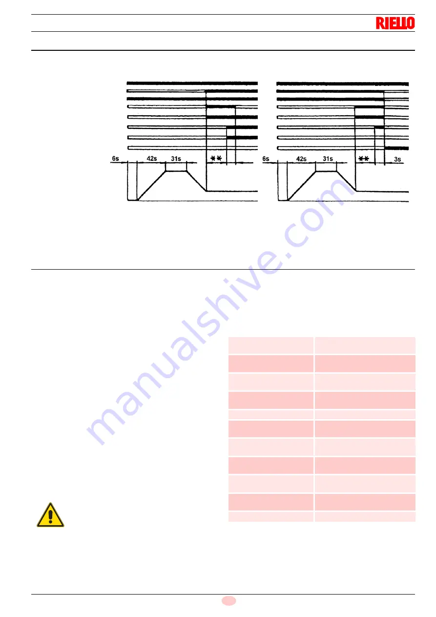
START-UP PROGRAM
(*) oil only
(**) Adjusted by timer 6)(Fig. 2) for oil (6s for gas operations)
MOTOR LOCK:
this is brought about by the overload cut-out thermic relay when a phase is missing.
SAFETY TEST - WITH GAS BALL VALVE CLOSED
It is fundamental to ensure the correct execution of the electrical
connections between the gas solenoid valves and the burner to
perform safely the commissioning.
For this purpose, after checking that the connections have been
carried out in accordance with the burner's electrical diagrams,
an ignition cycle with closed gas ball valve -dry test- must be per-
formed.
1
The manual ball gas valve must be closed
2
The electrical contacts of the burner limit switch need to be
closed
3
Ensures closed the contact of the low gas pressure switch
4
Make a trial for burner ignition
The start-up cycle must be as follows:
–
Starting the fan for pre-ventilation
–
Performing the gas valve seal control, if provided
–
Completion of pre-ventilation
–
Arrival of the ignition point
–
Power supply of the ignition transformer
–
Electrical Supply of solenoid gas valves
Since the manual gas ball valve is closed, the burner will not light
up and its control box will go to a safety lockout condition.
The actual electrical supply of the solenoid gas valves can be ver-
ified by inserting a tester. Some valves are equipped with light
signals (or close/open position indicator) that turn on at the same
time as their power supply.
SAFETY COMPONENTS
The safety components must be replaced at the end of their life
cycle indicated in Tab. A. The specified life cycles do not refer to
the warranty terms indicated in the delivery or payment condi-
tions.
Tab. A
Fig. 22
Normal
Lock for start-up failure
Control system
Pump motor
Fan motor
Transformer
(*) Pre-wash valve
Start-up valve
Flame
Lock
S7978
IF THE ELECTRICAL SUPPLY OF THE GAS
VALVES OCCURS AT UNEXPECTED TIMES,
DO NOT OPEN MANUAL GAS BALL VALVE,
SWITCH OFF POWER LINE; CHECK THE
WIRES; CORRECT THE ERRORS AND RE-
PEAT THE COMPLETE TEST.
Safety component
Life cycle
Flame control
10 years or 250,000
operation cycles
Flame sensor
10 years or 250,000
operation cycles
Gas valves (solenoid)
10 years or 250,000
operation cycles
Pressure switches
10 years or 250,000
operation cycles
Pressure adjuster
15 years
Servomotor (electronic
cam) (if present)
10 years or 250,000
operation cycles
Oil valve (solenoid) (if
present)
10 years or 250,000
operation cycles
Oil regulator (if present)
10 years or 250,000
operation cycles
Oil pipes/ couplings
(metallic) (if present)
10 years
Flexible hoses (if present)
5 years or 30,000 pressurised
cycles
Fan impeller
10 years or 500,000 start-ups
Summary of Contents for EMME 1400
Page 2: ......
Page 67: ...17 2915041 I IMPIANTO ELETTRICO ESEGUITO IN FABBRICA ENNE EMME 1400 2000 3000 SQM 40...
Page 74: ...2915041 24 I IMPIANTO ELETTRICO ESEGUITO IN FABBRICA ENNE EMME 4500 SQM 40...
Page 76: ...2915041 26 I IMPIANTO ELETTRICO ESEGUITO IN FABBRICA ENNE EMME 4500 SQM 10...
Page 85: ......
Page 86: ......
Page 87: ......


