22
MERKE
Der Stellantrieb folgt der Einstellung von Nok-
ken III nur bei Reduzierung des Winkels. Zur
Vergrößerung des Nockenwinkels zuerst durch
die Taste “Leistungserhöhung” den Winkel des
Stellantriebs vergrößern, dann den Nockenwin-
kel III vergrößern und schließlich durch die
Taste “Leistungsminderung” den Stellantrieb auf
Mindestleistungsstellung zurückgehen lassen.
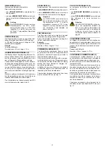
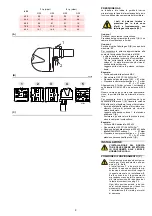
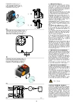
Zur Einstellung des Nocken III ist der eingera-
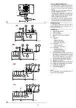
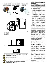
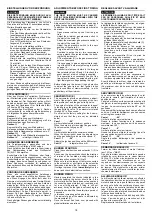
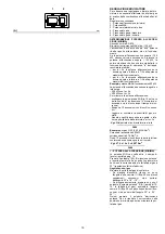
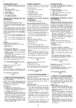
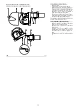
stete Deckel 1), s. Abb.(B) abzunehmen, die ent-
sprechende Passfeder 2) herauszuziehen und in
den Schlitz des Nocken III einzustecken.
Lufteinstellung
Das Anfangsprofil des Nocken 4)(A) über die
Nockenschrauben in der Öffnung 6)(A) verän-
dern. Die erste Schraube möglichst nicht ver-
drehen, mit dieser wird die Luftklappe ganz
geschlossen.
2 - HÖCHSTLEISTUNG
Die Höchsteistung ist im Regelbereich auf Seite
14 auszuwählen.
In der vorhergehenden Beschreibung ist der
Brenner auf der Mindestleistung in Betrieb
geblieben. Nun auf die Taste 2)(A)S.26 “Lei-
stungssteigerung” drücken, bis der Stellantrieb
gleichzeitig die Luftklappe und die Gasdrossel
auf 90° geöffnet hat auf 90°.
Gaseinstellung
Den Gasdurchsatz am Zähler messen.
Als Richtwert ist der Durchsatz aus den Tabellen
auf Seite 16 zu entnehmen, einfach den Gas-
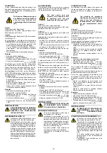
druck am Manometer, s. Abb. (D)S. 24, ablesen
und die Hinweise auf Seite 17 befolgen.
- Falls er herabgesetzt werden muß, den Aus-
trittsgasdruck verringern, und, wenn er schon
auf dem Mindestdruckwert ist, das Regelven-
til VR etwas schließen.
- Falls er erhöht werden muß, den Austrittsgas-
druck erhöhen.
Lufteinstellung
Über die Schrauben des Nocken im Inneren der
Öffnung 6)(A) das Endprofil des Nocken 4)(A)
verändern.
- Zur Erhöhung des Luftdurchsatzes die
Schrauben zudrehen.
- Zur Reduzierung des Luftdurchsatzes die
Schrauben abdrehen.
3 - ZWISCHENLEISTUNGEN
Gaseinstellung
Keine Einstellung ist erforderlich.
Lufteinstellung
Auf die Taste 2)(A)S.26 “Leistungserhöhung”
leicht drücken, so daß eine neue Schraube
5)(A) innerhalb der Öffnung 6)(A) sichtbar ist.
Die Schraube einstellen , bis eine optimale Ver-
brennung erreicht wird. Mit den anderen
Schrauben gleich verfahren.
Darauf achten, daß die Änderung des Nocken-
profils progressiv ist.
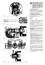
Brenner durch Schalter 1)(A)S.26, Stellung OFF,
abschalten, den Nocken mit variablem Profil
durch vertikale Positionierung des Schlitzes
2)(A) am Stellantrieb entsperren, und den Nok-
ken mehrmals von Hand vor- und zurückdrehen:
die Bewegung muß sanft und ungehindert erfol-
gen.
Darauf achten, daß die Schrauben an den
Enden des vorab eingestellten Nockens für die
Öffnung der Luftklappe auf der Höchst- und Min-
destleistung nicht versetzt werden.
MERKE
Nach Einstellung der Höchst-, Mindest- und
Zwischenleistungen ist die Zündung nochmals
zu überprüfen. Der Schalldruckpegel muß dem
der anschließenden Betriebsphase entspre-
chen. Bei Verpuffungen sollte der Zünddurch-
satz reduziert werden.
NOTE
The servomotor follows the adjustment of cam
III only when the cam angle is reduced. If it is
necessary to increase the cam angle, first
increase the servomotor angle with the key “out-
put increase”, then increase the cam III angle,
and at the end bring the servomotor back to the
MIN output position with the key ”output
decrease”.
In order to adjust cam III, remove press-fit cover
1), as shown in fig.(B), extract the relevant key 2)
from inside, and fit it into the keyway in cam III.
Adjustment of air delivery
Progressively adjust the starting profile of cam
4)(A) by turning the screws working through the
access hole 6)(A).
It is preferable not to turn the first screw since
this is used to set the air gate valve to its fully-
closed position.
2 - MAX. OUTPUT
Max. output of the burner must be set within the
firing rate range shown on page 14.
In the above instructions we left running in MIN.
output operation. Now press button 2)(A)p.26
“increase output” and keep it pressed until the
servomotor has opened the air gate valve and
the gas butterfly valve by 90°.
Gas calibration
Measure the gas delivery at the meter.
A guideline indication can be calculated from the
tables on page 16, simply read off the gas pres-
sure on the manometer, see fig. (D) on page 24,
and follow the instructions on page 17.
- If delivery needs to be reduced, decrease the
outlet gas pressure and, if it is already very
low, slightly close adjustment valve VR.
- If delivery needs to be increased, increase
outlet gas pressure.
Adjusting air delivery
Progressively adjust the end profile of cam 4)(A)
by turning the cam adjustment screws as they
appear through the access opening 6)(A).
- Turn the screws clockwise to increase air
delivery.
- Turn the screws anti-clockwise to reduce air
delivery.
3 - INTERMEDIATE OUTPUTS
Adjustment of gas delivery
No adjustment of gas delivery is required.
Adjustment of air delivery
Press the key 2)(A)p.26 “output increase” a little
so that a new screw 5)(A) appears in the open-
ing 6)(A), adjust it until optimal combustion is
obtained. Proceed in the same way with the
other screws.
Take care that the cam profile variation is pro-
gressive.
Switch the burner off with the switch 1)(A)p.26,
free the variable profile cam putting the servo-
motor slot 2)(A) in a vertical position and check
more than once, rotating the cam forward and
backward by hand, that the movement is soft
and smooth, without sticking.
As far as is possible, try not to move those
screws at the ends of the cam that were previ-
ously adjusted for the opening of the air gate to
MAX and MIN output.
NOTE
Once you have finished adjusting outputs MAX -
MIN - INTERMEDIATE, check ignition once
again: noise emission at this stage must be
identical to the following stage of operation. If
you notice any sign of pulsations, reduce the
ignition stage delivery.
NOTE
Le servomoteur ne suit le réglage de la came
III que quand on réduit l'angle de la came. Avant
d’augmenter l’angle de la came, augmenter
d’abord augmenter l’angle du servomoteur avec
le bouton “augmentation de la puissance”, aug-
menter ensuite l’angle de la came IIII et enfin
reporter le servomoteur en position de puis-
sance MIN avec le bouton “diminution de la
puissance”.
Pour régler éventuellement la came III, enlever
le couvercle 1) enclenché par pression comme
indiqué sur la fig. (B), retirer la clavette 2) située
à l’intérieur et placer celle-ci dans la fente de la
came III.
Réglage de l'air
Modifier en progression le profil initial de la
came 4)(A) en agissant sur les vis de celle-ci qui
apparaissent à l’intérieur de l’ouverture 6)(A). Si
possible, Ne pas serrer la première vis, si pos-
sible il s'agit de la vis qui ferme complètement le
volet de l'air.
2 - PUISSANCE MAXIMUM
La puissance maximum doit être choisie dans la
plage indiqué à la page 14.
La description qui précède concerne un brûleur
allumé et fonctionnant à la puissance minimum.
Appuyer ensuite sur le bouton 2)(A)p.26 “aug-
mentation de la puissance” sans le relâcher et
continuer à appuyer jusqu’à ce que le servomo-
teur ouvre le volet d’air et la vanne papillon du
gaz à 90°.
Réglage du gaz
Mesurer le débit du gaz sur le compteur.
A titre indicatif, ce débit peut être trouvé sur les
tableaux à la page 16. Il suffit de lire la pression
du gaz sur le manomètre, comme indiqué fig.
(D) page 24,et de suivre les indications de la
page 17.
- Diminuer la pression du gaz à la sortie s'il faut
la réduire et fermer légèrement la vanne de
réglage si elle est déjà au minimum. fermer
un peu la vanne de réglage VR.
- Augmenter la pression du gaz à la sortie s’il
faut l’augmenter.
Réglage air
Modifier en progression le profil final de la came
4)(A) en agissant sur les vis de celle-ci qui
apparaissent à l’intérieur de l’ouverture 6)(A).
- Pour augmenter le débit d'air serrer les vis.
- Pour diminuer celui-ci, desserrer les vis.
3 - PUISSANCES INTERMEDIAIRES
Réglage du gaz
Aucun réglage n'est nécessaire.
Réglage de l'air
Appuyer légèrement sur le bouton 2)(A)p.26
“augmentation de la puissance” afin qu’une nou-
velle vis 5)(A) apparaise à l’intérieur de l’ouver-
ture 6)(A), la régler pour obtenir une combustion
parfaite. Procéder de la même façon avec les
vis successives.
Contrôler si la variation du profil de la came est
progressive.
Eteindre le brûleur en actionnant l'interrupteur
1)(A)p.26, position OFF, détacher la came à pro-
fil variable en mettant la fente 2)(A) du servomo-
teur en position verticale et contrôler plusieurs
fois, en tournant manuellement la came vers
l’avant et vers l’arrière, si le mouvement est
souple et sans accrocs.
Si possible, faire en sorte veiller à ne pas dépla-
cer les vis aux extrémités car elles ont été
réglées précédemment pour l'ouverture du volet
à la puissance MAX. et MIN.
NOTE
Contrôler l’allumage dès que le réglage des
puissances MAX – MIN – intermédiaires est ter-
miné. Celui-ci doit produire un son identique au
son du fonctionnement qui s'ensuit. En cas de
saccades, Réduire le débit à l’allumage en cas
de saccades.

