6
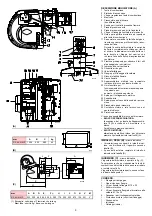
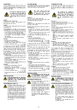
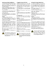
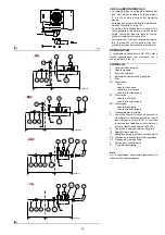
BRENNERBESCHREIBUNG (A)
1 Flammkopf
2 Zündelektrode
3 Einstellschraube des Flammkopfes
4 Muffe
5 Mindestluftdruckwächter
(Differentialtyp)
6 Flammenfühler
7 Luftdruckentnahmestelle
8 Gasdruckentnahmestelle und Befestigungs-
schraube des Flammkopfes
9 Befestigungsschraube des Gebläses an der
Muffe
10 Gleitschienen zur Öffnung des Brenners und
für die Kontrolle des Flammkopfs
11 Stellantrieb zur Steuerung der Gasdrossel
und, über einen Nocken mit variablem Profil,
der Luftklappe.
Bei Brennerstillstand ist die Luftklappe voll-
ständig geschlossen, um die Wärmeverluste
des Kessels durch den Kaminzug mit Luft-
nachführung von der Saugöffnung des
Gebläses zu vermeiden.
12 Platte mit 4 Vorbohrungen, zum Durchtritt
der Stromkabel
13 Lufteinlaß zum Gebläse
14 Gaszuleitung
15 Gasdrossel
16 Befestigungsflansch am Kessel
17 Stauscheibe
18 Flammen-Sichtfenster
19 Steuergerät mit Kontrollampe für Störab-
schaltung und Entriegelungsschalter
20 Ein Schalter für:
Automatischer Betrieb-Manueller Betrieb-Aus
Ein Schalter für:
Leistungsmindeung - Leistungabminderung
21 Anschlußstecker
22 Luftklappe
23 Steckanschluß am Kabel des
Ionisationsfühlers.
24 Gas-höchstdruckwächter
25 Motorschütz und Überstromauslöser mit
Entriegelungsschalter
26 Motorschutz
Die Störabschaltungen des Brenners können
zweierlei Art sein:
• STÖRABSCHALTUNG DES GERÄTES:
Das Aufleuchten des Druckknopfes des Gerä-
tes 19)(A) weist auf eine Störabschaltung des
Brenners hin.
Zur Entriegelung den Druckknopf drücken.
• STÖRABSCHALTUNG DES MOTOR :
Dreiphasing-Stromversongung, Entriegelung
durch Drücken auf den Druckknopf des Über-
stromauslösers 25)(A).
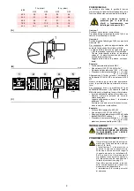
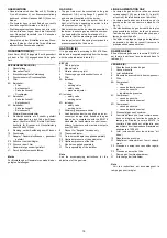
VERPACKUNG - GEWICHT (B)
- Richt-
werte
• Die Brenner werden in Kartonverpackungen
geliefert, Abmessungen siehe Tabelle (B).
• Das Gesamtgewicht des Brenners einschließ-
lich Verpackung ist in Tabelle (B) angegeben.
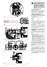
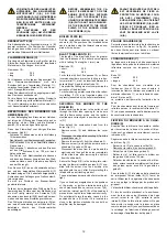
ABMESSUNGEN (C)
- Richtwerte
Die Brennerabmessungen sind in Abb. (C) ange-
führt.
Zur Inspektion des Flammkopfes muß der Bren-
ner
zurückgeschoben
und
nach
oben
geschwenkt werden.
Die Abmessungen des offenen Brenners, ohne
Verkleidung, sind unter Hangegeben.
AUSRÜSTUNG
1 - Flansch für Gasarmaturen
1 - Dichtung für Flansch
4 - Schrauben für die Befestigung des
M 10 x 35 Flansches
1 - Wärmeschild
4 - Schrauben für die Befestigung des Bren-
nerflanschs am Kessel: M 12 x 35
5 - Kabeldurchgänge für Elektroanschluß
1 - Motorschutz (mit Befestigungsschraube)
1 - Stiftgruppe
1 - Anleitung
1 - Ersatzteilekatalog
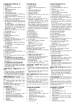
DESCRIPTION (A)
1 Combustion head
2 Ignition electrode
3 Screw for combustion head adjustment
4 Sleeve
5 Minimum air pressure switch
(differential operating type)
6 Flame sensor probe
7 Air pressure test point
8 Gas pressure test point and head fixing
screw
9 Screw securing fan to sleeve
10 Slide bars for opening the burner and
inspecting the combustion head
11 Servomotor controlling the gas butterfly
valve and air gate valve (by means of a vari-
able profile cam mechanism).
When the burner is stopped the air gate valve
will be completely closed to reduce to a mini-
mum heat loss due to the flue draught: the lat-
ter tends to draw air from the fan suction inlet.
12 Plate with 4 hole knock-outs for electrical
cable routing
13 Air inlet to fan
14 Gas input pipework
15 Gas butterfly valve
16 Boiler mounting flange
17 Flame stability disk
18 Flame inspection window
19 Control box with lock-out pilot light and lock-
out reset button
20 Power switch for different operations:
automatic - manual - off
Button for:
power increase - power reduction.
21 Plugs for electrical connections
22 Air gate valve
23 Plug-socket on ionisation probe cable
24 Maximum gas pressure switch
25 Motor contact maker and thermal cutout with
reset button
26 Engine protection
Two types of burner failure may occur:
• CONTROL BOX LOCK-OUT:
if the control box 19)(A) pushbutton lights up,
it indicates that the burner is in lock-out.
To reset, press the pushbutton.
• MOTOR LOCKOUT:
three-phase electrical supply; to unblock,
press the thermal cutout switch 25)(A).
PACKAGING - WEIGHT (B)
- Approximate
measurements
• The burners are shipped in cardboard boxes
with the maximum dimensions shown in table
(B).
• The weight of the burner complete with pack-
aging is indicated in table (B).
MAX. DIMENSIONS (C)
-
Approximate mea-
surements
The maximum dimensions of the burner are
given in (C).
Note that if you need to examine the combustion
head, the burner must be pulled backward on
the slide bars and turned upward.
The maximum dimension of the burner, without
the cover, when open is give by measurement
H.
STANDARD EQUIPMENT
1 - Gas train flange
1 - Flange gasket
4 - Flange fixing screws M 10 x 35
1 - Thermal insulation screen
4 - Screws to secure the burner flange to the
boiler: M 12 x 35
5 - Fairleads for electrical connections
1 - Engine protection (with fixing screws)
1 - Plugs unit
1 - Instruction booklet
1 - Spare parts list
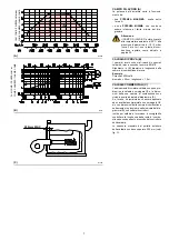
DESCRIPTION BRULEUR (A)
1 Tête de combustion
2 Electrode d'allumage
3 Vis pour réglage tête de combustion
4 Manchon
5 Pressostat air seul minimum
(type différentiel)
6 Sonde de contrôle présence flamme
7 Prise de pression air
8 Prise de pression gaz et vis de fixation tête
9 Vis de fixation ventilateur au manchon
10 Guides pour ouverture brûleur et inspection
de la tête de combustion
11 Servomoteur de commande de la vanne
papillon du gaz et, par came à profil variable,
du volet d'air.
Lors de l'arrêt du brûleur, le volet d'air est
totalement fermé pour réduire au minimum
les déperditions de chaleur de la chaudière
dues au tirage de la cheminée qui aspire l’air
sur la bouche d'aspiration du ventilateur.
12 Plaquette prévue avec 4 trous passe-câbles
13 Entrée d’air dans le ventilateur
14 Canalisation d'arrivée du gaz
15 Vanne papillon gaz
16 Bride de fixation à la chaudière
17 Disque de stabilité de la flamme
18 Viseur flamme
19 Coffret de sécurité avec signal lumineux de
blocage et bouton de déblocage
20 Un interrupteur pour le fonctionnement:
automatique - manuel - éteint
Un bouton pour:
augmentation - diminution de puissance.
21 Fiches de branchement électrique
22 Volet d'air
23 Fiche-prise sur câble sonde d’ionisation
24 Pressostat gaz maximum
25 Contacteur moteur et relais thermique avec
bouton de déblocage
26 Protection du moteur
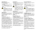
Il existe deux types de blocage du brûleur:
• BLOCAGE COFFRET:
l'allumage du bouton du coffret de sécurité
19)(A) signale que le brûleur s'est bloqué.
Pour le débloquer appuyer sur le bouton.
• BLOCAGE MOTEUR:
alimentation électrique triphasée; pour le
débloquer appuyer sur le bouton-poussoir du
relais thermique 25)(A).
EMBALLAGE - POIDS (B)
- Mesures indica-
tives
• Les brûleurs sont expédiés dans des embal-
lages en carton dont les dimensions d'encom-
brement sont indiquées dans le tableau (B).
• Le poids du brûleur avec son emballage est
indiqué dans le tableau (B).
ENCOMBREMENT (C)
- Mesures indicatives
L'encombrement du brûleur est indiqué dans le
tab. (C).
Attention: pour inspecter la tête de combustion,
le brûleur doit être reculé et tourné vers le haut.
L’encombrement du brûleur ouvert, sans carter,
est indiqué par la cote H.
EQUIPEMENT STANDARD
1 - Bride pour rampe gaz
1 - Joint pour bride
4 - Vis de fixation bride M 10 x 35
1 - Ecran thermique
4 - Vis pour fixer la bride du brûleur à la chau-
dière: M 12 x 35
5 - Passe-câbles pour branchement électrique
1 - Protection du moteur (avec vis de fixation)
1 - Groupe fiches
1 - Instructions
1 - Catalogue pièces détachées


