14
INStAllAtION
A
Pipe Ø
A
mm
inches
mm
6,35
1/4
9,1
9,52
3/8
13,2
12,70
1/2
16,6
15,88
5/8
19,7
1
Key
2
Torque wrench
3
Flare nut
2
3
1
Pipe Ø
tightening torque
mm
inches
Nm
6,35
1/4
18
9,52
3/8
42
12,70
1/2
55
15,88
5/8
60
A
Pipe Ø
A
mm
inches
mm
6,35
1/4
17
9,52
3/8
22
12,70
1/2
26
15,88
5/8
29
—
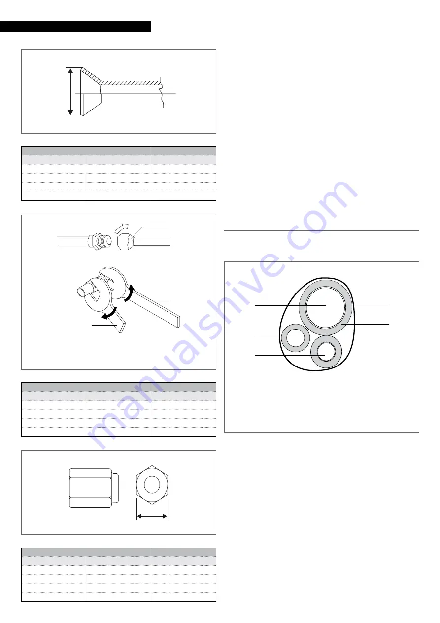
bring line ends with flare connection close to their cou-
pling on the unit
—
manually rotate the flare nuts by 3 - 4 turns
—
tighten the connections using a spanner and a counter
spanner
9
Use a torque wrench to tighten so as to prevent damage to
flare nuts and gas leaks.
9
Use equipment suitable for the system refrigerant.
9
Avoid using the refrigerant oil on the external part of the
flaring.
9
Avoid proximity to sources of ignition in continuous op-
eration (open flames, gas household appliances, electric
stoves, etc.).
9
As for circuit leak and pneumatic vacuum tests, refer to the
matching outdoor unit instruction booklet for the installer.
Pipe insulation
Connection pipes must be thermally insulated to prevent dis-
persions of heat or formation of condensate.
1
Gas pipe
2
Condensation discharge
3
Liquid pipe
4
Heat insulation
5
Adhesive tape
5
4
4
1
2
3
—
insulate the liquid and gas pipes separately
—
use insulating material that is thicker than 15 mm
—
ensure that the insulating material adheres to the pipe
without gaps
—
fix using adhesive tape
9
Do not tighten the adhesive tape too much, so as to avoid
damaging the insulation.
9
Avoid partial insulation of the pipes.
9
In case of use with outdoor temperature above 30 °C and
relative humidity above 80%, increase wall thickness up to
20 mm.
For gas pipes:
—
ensure that the material used resists to temperatures up
to 120°C
For liquid pipes:
—
ensure that the material used resists to temperatures up


