background image

7

SYMBOLS

Indicates an imminently hazardous situation, which, if not avoided, will 
result in death or serious injury.

Indicates a potentially hazardous situation, which, if not avoided, could 
result in death or serious injury.

Indicates a potentially hazardous situation, which, if not avoided, may 
result in minor or moderate injury. 

(Without Safety Alert Symbol) Indicates a situation that may result in 
property damage.


SYMBOL  

SIGNAL 


MEANING

SERVICE

Servicing requires extreme care and knowledge and should 
be  performed  only  by  a  qualified  service  technician.  For 
service we suggest you return the product to your nearest 

AUTHORIZED SERVICE CENTER

 for repair. When servic-

ing, use only identical replacement parts.


WARNING:

To avoid serious personal injury, do not attempt 
to use this product until you read thoroughly and 
understand  completely  the  operator’s  manual. 
If  you  do  not  understand  the  warnings  and 
instructions in the operator’s manual, do not use 
this  product.  Call  RIDGID  customer  service  for 
assistance.

The operation of any power tool can result in foreign objects being thrown into your eyes, which can result 
in severe eye damage. Before beginning power tool operation, always wear safety goggles or safety glasses 
with side shields and, when needed, a full face shield. We recommend Wide Vision Safety Mask for use 
over eyeglasses or standard safety glasses with side shields. Always use eye protection which is marked 
to comply with ANSI Z87.1.


WARNING:

SAVE THESE INSTRUCTIONS

DANGER:

CAUTION:

CAUTION:

WARNING:

The following signal words and meanings are intended to explain the levels of risk associated with this product.

Summary of Contents for TS2400LS

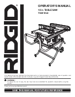
Page 1: ...afety When properly cared for it will give you years of rugged trouble free performance WARNING To reduce the risk of injury the user must read and understand the operator s manual before using this product Thank you for buying a RIDGID product OPERATOR S MANUAL 10 in TABLE SAW TS2410LS SAVE THIS MANUAL FOR FUTURE REFERENCE ...

Page 2: ... Operation 20 34 Adjustments 35 39 Maintenance 40 41 Accessories 41 Troubleshooting 42 43 Warranty 45 Parts Ordering Service Back Page TABLE OF CONTENTS This tool has many features for making its use more pleasant and enjoyable Safety performance and dependability have been given top priority in the design of this product making it easy to maintain and operate INTRODUCTION ...

Page 3: ...eyeglasses have only impact resistant lenses they are NOT safety glasses SECURE WORK Use clamps or a vise to hold work when practical It s safer than using your hand and frees both hands to operate tool DON T OVERREACH Keep proper footing and balance at all times MAINTAIN TOOLS WITH CARE Keep tools sharp andcleanforbetterandsaferperformance Followinstruc tions for lubricating and changing accessor...

Page 4: ...ITH THE WORKPIECE DO NOT OPERATE A TOOL WHILE UNDER THE INFLUENCE OF DRUGS ALCOHOL OR ANY MEDICATION WHENSERVICINGuse only identical replacement parts Use of any other parts may create a hazard or cause product damage USE ONLY RECOMMENDED ACCESSORIES listed in this manual or addendums Use of accessories that are not listed may cause the risk of personal injury Instructions for safe use of accessor...

Page 5: ...ck pawls and blade guard in place and operating d Not releasing the work before it is pushed all the way past the saw blade using a push stick e Not ripping work that is twisted or warped or does not have a straight edge to guide along the fence IF THE POWER SUPPLY CORD IS DAMAGED it must be replaced only by the manufacturer or by an authorized service center to avoid risk AVOID AWKWARD OPERATIONS...

Page 6: ...se in damp locations To reduce the risk of injury user must read and understand operator s manual before using this product Eye Protection Always wear safety goggles or safety glasses with side shields and as necessary a full face shield when operating this product Precautions that involve your safety Failure to keep your hands away from the blade will result in serious personal injury Wet Conditi...

Page 7: ...NG To avoid serious personal injury do not attempt to use this product until you read thoroughly and understand completely the operator s manual If you do not understand the warnings and instructions in the operator s manual do not use this product Call RIDGID customer service for assistance The operation of any power tool can result in foreign objects being thrown into your eyes which can result ...

Page 8: ... A substantial voltage drop will cause a loss of power and the motor will overheat If the saw does not operate when plugged into an outlet double check the power supply SPEED AND WIRING The no load speed of this tool is approximately 4 000 rpm This speed is not constant and decreases under a load or with lower voltage For voltage the wiring in a shop is as important as the motor s horsepower ratin...

Page 9: ... being dropped into the blade or being placed inadvertently in contact with the blade Workpiece or Material The item on which the operation is being done Worktable Surface where the workpiece rests while performing a cutting drilling planing or sanding operation Anti Kickback Pawls radial arm and table saws A device which when properly installed and maintained is designed to stop the workpiece fro...

Page 10: ...SCALE MITER GAUGE Fig 3 LEG STAND BEVEL INDICATOR BLADE HEIGHT LOCK KNOB PRODUCT SPECIFICATIONS Blade Diameter 10 in Blade Arbor 5 8 in Cutting Depth at 90 3 1 8 in Cutting Depth at 45 2 1 4 in Rating 120 V AC Only 60 Hz 15 Amps Output Speed 4 000 r min RPM RIP FENCE BLADE AND BLADE WRENCH STORAGE BLADE WRENCH BEVEL LOCKING LEVER TABLE EXTENSION GRIPS ...

Page 11: ...ade for through sawing cuts BLADE HEIGHT LOCK KNOB This knob in the center of the height bevel adjusting handwheel locks the blade in place BEVEL LOCKING LEVER This lever under the worktable surface on the front of the cabinet locks the angle setting of the blade HEIGHT BEVEL ADJUSTING HANDWHEEL Located on the front of the cabinet this handwheel is used to lower and raise the blade for adjustments...

Page 12: ... cuts A scale on the front rail shows the distance between the rip fence and the blade It is very important to use the blade guard assembly for all through sawing operations The blade guard assembly includes spreader splitter anti kickback pawls and plastic blade guard SWITCH ASSEMBLY This saw is equipped with a switch assembly that has a built in locking feature This feature is intended to preven...

Page 13: ... for assembly and adjustments COMBINATION WRENCH 4 3 8 in 7 16 in 1 2 in 9 16 in Fig 5 PHILLIPS SCREWDRIVER HEX KEYS 3 3 32 in 5 32 in 3 16 in COMBINATION SQUARE RIP FENCE MITER GAUGE BLADE GUARD ASSEMBLY SWITCH KEY The following items are included with your table saw FRAMING SQUARE ...

Page 14: ...t to power supply until assembly is complete Failure to comply could result in ac cidental starting and possible serious personal injury WARNING Do not lift the saw without help Hold it close to your body Keep your knees bent and lift with your legs not your back Ignoring these precau tions can result in back injury WARNING Never stand directly in line with the blade or allow hands to come closer ...

Page 15: ... leg stand is released from the release lever ease the leg stand toward the floor by pushing the grips toward the floor With your hands on the grips push the leg stand towards the ground until the table saw is in an open position NOTE The release lever will close over the center brace locking the leg stand in an open position Fig 7 Fig 8 Fig 9 GRIPS LEG STAND CENTER BRACE RELEASE LEVER RELEASE LEV...

Page 16: ...age areas specifically designed for the saw s accessories These accessories must be securely stored prior to closing the leg stand and moving the saw Alwaysstorethebladeguardwhenmakingnon throughcuts and or transporting the saw Slide blade guard in storage area Snap bottom edge of clear basket between latches on base To store the rip fence place the top edge in first and twist downward to snap int...

Page 17: ...saw blade To close the leg stand At the same time step on the release lever grasp the grips and lift the handles up and away from the body Push the table saw until the release lever clicks and locks into place To move the leg stand Holding the grips firmly pull the handles toward you until the leg stand and saw are balanced on the wheels Push the saw to the desired location then either open the le...

Page 18: ...igure 16 Retightenthescrewbeingcarefulnottoovertightenwhich can cause the throat plate to bow or bend TO REMOVE REPLACE THE THROAT PLATE See Figure 17 Unlock the blade height lock knob Lower the blade by turning the height bevel adjusting handwheel counterclockwise Loosen the screw in the throat plate Lift the throat plate from the front end and pull toward the front of the saw Place throat plate ...

Page 19: ... the machine To tighten the blade Using the smaller blade wrench place the flat open end into the flats on the arbor shaft Insert the closed end of the larger blade wrench over the hex nut Holding both wrenches firmly push the larger wrench to the back of the machine Make sure the blade nut is securely tightened Do not overtighten Check all clearances for free blade rotation Refer to To Check and ...

Page 20: ...ade by turning the height bevel adjusting handwheel counterclockwise From the back of the saw loosen the hex head bolts and reposition the blade guard assembly left or right as needed to align the spreader with the saw blade Once properly aligned securely retighten the bolts Recheck the marked blade tooth to insure the adjustment has not moved OPERATION WARNING Do not allow familiarity with tools ...

Page 21: ... blade for the type of cut Not following correct operating procedures Misusing the saw Failing to use the anti kickback pawls Cutting with a dull gummed up or improperly set blade AVOIDING KICKBACK Always use the correct blade depth setting The top of the blade teeth should clear the workpiece by 1 8 in to 1 4 in Inspect the work for knots or nails before beginning a cut Knock out any loose knots ...

Page 22: ...h stick with small pieces of wood and also to finish the cut when ripping a long narrow piece of wood to prevent your hands from getting close to the blade Bevel cuts are made with an angled blade Bevel cross cuts are across the wood grain and bevel rip cuts are with the grain The rip fence must always be on the right side of the blade for bevel rip cuts Compound or bevel miter cuts are made with ...

Page 23: ...30 Set the rip fence to allow approximately a 1 4 in finger to be cut in the stock Feed the stock only to the mark previously made at 6 in Turn the saw OFF and allow the blade to completely stop rotating before removing the stock Reset the rip fence andcutspacedripsintotheworkpiecetoallowapproximately 1 4 in fingers and 1 8 in spaces between the fingers HOW TO MOUNT A FEATHERBOARD See Figure 24 Co...

Page 24: ...ded for marking the location of the saw cut kerf on the workpiece The disc should be level or slightly below the surface of the saw table Place a piece of hardwood over the plastic disc and tap the hardwood with a hammer until the disc is level or below the saw table surface Once the Ind I Cut is level From the front of the table saw place the miter gauge in the left miter groove and move the heig...

Page 25: ...e the fence When securely locked the locking lever should point downward Checkforasmoothglidingaction Ifadjustmentsareneeded see To Check and Adjust the Alignment of the Rip Fence in the Adjustments section of this manual TO USE THE MICRO ADJUST WHEEL ON THE RIP FENCE See Figure 29 The micro adjust wheel on the rip fence allows the user to make one handed adjustments To use the micro adjust wheel ...

Page 26: ... be located by pushing in the stop pin Slide the miter gauge in the miter gauge slot Loosen the lock knob by turning it counterclockwise Pull out the stop pin and rotate the gauge until the desired angle is reached on the scale Retighten the lock knob by turning it clockwise TO USE THE TABLE EXTENSION See Figure 31 Increase the length of the saw table by using the table extension NOTE The table ex...

Page 27: ...the blade tooth to the right miter gauge groove If the distances are the same the blade and the miter gauge groove are parallel Loosen the four alignment screws 1 2 turn this allows the mechanism beneath the table to be shifted sideways NOTE The adjusting screws are located on the top of the saw table next to the blade Place a block of wood on the side of the blade and push it into the blade until...

Page 28: ...orking properly to avoid serious personal injury Remove the rip fence by lifting the locking lever Set the blade to the correct depth for the workpiece Set the miter gauge to 0 and tighten the lock knob Place a support the same height as saw table behind the saw for the cut work Make sure the wood is clear of the blade before turning on the saw To turn the saw ON lift the switch To turn saw OFF pr...

Page 29: ...d through thecutpasttheblade Neverpushasmallpieceofwood intothebladewithyourhand Alwaysuseapushstick The use of push blocks push sticks and featherboards are necessary when making non through cuts Stand to the side of the wood as it contacts the blade to reduce the chance of injury should kickback occur Never stand directly in the line of cut Make sure the wood is clear of the blade before turning...

Page 30: ...port the same height as saw table behind the saw for the cut work Make sure the wood is clear of the blade before turning on the saw Let the saw blade build up to full speed before moving the miter gauge and the workpiece into the blade Hold the workpiece firmly with both hands and feed the workpiece into the blade NOTE The hand closest to the blade should be placed on the miter gauge lock knob an...

Page 31: ...t as the table surface behind the saw for the cut work Make sure the wood is clear of the blade before turning on the saw Position the workpiece flat on the table with the edge flush against the rip fence Let the blade build up to full speed before feeding the workpiece into the blade Using a push stick and or push blocks slowly feed the workpiece toward the blade Stand slightly to the side of the...

Page 32: ... for the blade to come to a complete stop before removing any part of the workpiece Afterthebladehasstoppedcompletely removethecutoff stock MAKING A LARGE PANEL CUT See Figure 43 Make sure the saw is properly secured to a work surface to avoid tipping from the weight of a large panel WARNING Make sure the blade guard assembly is installed and working properly to avoid serious personal injury Place...

Page 33: ... the appropriate section which describes the type of cut in addition to this section on non through or dado cuts For example if your non through cut is a straight cross cut read and understand the section on straight cross cuts before proceeding Unplug the saw Lower the blade and remove the screw holding the throat plate in place Remove the throat plate Raise the saw blade Unlock the bevel locking...

Page 34: ...he blade guard assembly throat plate and the saw blade Remove the inner blade washer and the spacer See Figure 47 Reinstall the inner blade washer Mount the dado blade using the blade and chippers appropriate for the desired width of cut Reinstall the arbor nut Make sure the arbor nut is fully engaged and the arbor extends at least one full thread past a securely tightened arbor nut When mounting ...

Page 35: ...ch insert the flat open end into the flats on the arbor shaft Insert the closed end of the larger wrench over the hex nut Holding both wrenches firmly pull the larger wrench forward to the front of the machine Make sure the arbor nut is securely tightened Do not overtighten NOTE Arbor shaft has left hand threads Check all clearances for free blade rotation Refer to To Set the Rip Fence Indicator t...

Page 36: ...hex key Release the bevel locking lever and position the height bevel adjusting handwheel until blade is 0º to the table Lock the bevel locking lever Screwthe0ºstopscrewuntilthesawbladestartstomove Check again for squareness and readjust if needed Check bevel indicator If indicator is not pointing to the 0º mark on the bevel scale loosen the indicator adjusting screw and adjust indicator Retighten...

Page 37: ...e at 0º and plus or minus 45º with the miter gauge stop pin and adjustable stop screws NOTE The miter gauge provides close accuracy in angled cuts For very close tolerances test cuts are recommended To adjust stop screws Loosen the lock knob and pull out on stop pin to rotate miter gauge base past stop screws Loosen the lock nut of the 0º stop screw at the stop pin with a wrench Place a 90º square...

Page 38: ...ternately tighten the hex head bolts Recheck align ment Repeat steps as needed until rip fence is correctly aligned The locking lever on the rip fence should hold the rip fence securely against the front and back rails The lever should not be difficult to push down and lock To assure proper fence lock adjustment Raise the locking lever and push rip fence toward rear of saw Hold rip fence down on t...

Page 39: ...sliding table extension should not move while locked If the extension moves Lift the table extension lock lever Find the front hex coupling located underneath the front table Loosen the hex locking nut Turn the hex coupling counterclockwise Lock the table extension lock Push and pull on the sliding table extension Readjust hex coupling if necessary Tighten the hex locking nut against coupling TO A...

Page 40: ...maintain the table surfaces and rails periodically apply paste wax to them and buff to provide smooth functioning To prevent work from slipping during cutting operations DO NOT wax the working face of the miter gauge Protect the saw blade by cleaning out sawdust from underneath the saw table and in the blade teeth Use a resin solvent on the blade teeth Clean plastic parts only with a soft damp clo...

Page 41: ...ury BRUSH REPLACEMENT See Figure 61 Unplug the saw Lower blade completely and bevel to 45º Lock the blade Turn saw upside down Remove brush caps with a screwdriver NOTE Brush assembly is spring load and will pop out when brush cap is removed Remove brush assemblies and check for wear Replace both brushes when either has less than 1 4 in length of carbon remaining Do not replace one side without re...

Page 42: ... Blade is heeling Work is fed too fast Rip fence is misaligned Separator is out of alignment Wood is warped Rip fence is misaligned Blade not properly aligned or set Replace blade Replace blade Tighten all hardware Reposition on flat surface Check saw blade installation Remount the rip fence Clean and wax rails Adjust clamp screw Adjust clamp screw Replace or sharpen blade Align rip fence miter ga...

Page 43: ...ype for cut being made Blade is mounted backwards Work is fed too fast motor overloaded Blade not proper for rip cut See To Set the Bevel Indicator and Bevel Stops at 0 and 45 Squaring the Blade in the Adjustments section See To Adjust the Miter Gauge in the Adjustments section Clean the gears or screw posts Unlock the height bevel adjusting handwheel by pushing the bevel lock lever to the right P...

Page 44: ...44 NOTES ...

Page 45: ... www ridgid com When requesting warranty service you must present the original dated sales receipt The authorized service center will re pair any faulty workmanship and either repair or replace any part covered under the warranty at our option at no charge to you One World Technologies Inc P O Box 35 Hwy 8 Pickens SC 29671 RIDGID HAND HELD AND STATIONARY POWER TOOL 3 YEAR LIMITED SERVICE WARRANTY ...

Page 46: ...ed service center nearest you please call 1 866 539 1710 or visit us online at www ridgidwoodworking com The model number of this tool is found on a plate attached to the motor housing Please record the serial number in the space provided below When ordering repair parts always give the following information Model No Serial No TS2410LS OPERATOR S MANUAL 10 in TABLE SAW TS2410LS 987000 213 10 18 07...

Reviews: