Ridge Tool Company
8
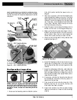
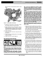
17. Pull the vent on the reservoir cap open
(Figure 6). Do
not thread with the vent closed. This will reduce
coolant flow and could cause die chipping and poor
quality threads.
Figure 6 – Reservoir Vent Open
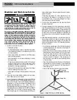
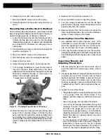
18. Move the die head down into the threading position.
Depress and hold the foot switch and look for coolant
flow between die 3 and 4 on the die head
(See Figure
7). It may take up to 10 seconds for the coolant to start
flowing if the die head has been off the machine or sat
for an extended time. Coolant should be dripping at a
rate of at least 1 drop per second. Too high a drip rate
wastes coolant, while too low a drip rate can cause die
chipping, poor quality thread and high thread temper-
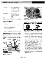
atures.
19. To adjust the coolant drip rate, while depressing the
foot switch, use a flat blade screwdriver to turn the
needle pin on the die head
(see Figure 7). Clockwise
needle pin rotation decreases drip rate, while coun-
terclockwise rotation increases drip rate
Figure 7 – Adjusting Coolant Drip Rate
20. Move the die head away from the operator. Die head
position turns the coolant flow on and off while ma-
chine is running. To conserve coolant, only place die
head down in the threading position when threading or
transporting.
21. Move the ON/OFF switch to the OFF position, and
with dry hands unplug the machine.
Installing Dies and Adjusting For Size In
No. 610 Quick-Opening Die Head
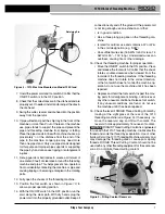
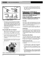
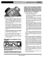
The 610 quick-opening die head
(Figure 8) uses one set
of dies for
1
/
2
" and
3
/
4
" threads and another set for 1"
threads. Dies are available for NPT and BSPT thread
forms.
The 610 Die Head is designed for use ONLY with the
1210 Threading Machine. This die head is not compati-
ble with any other RIDGID threading equipment. No
other RIDGID die heads will fit on the Model 1210
Threading Machine.
1. With machine unplugged, rotate the die head retaining
knob
(Figure 7) on the carriage counterclockwise to
unlock the die head post. Remove the die head from
the carriage.
Figure 8 – No. 610 Quick-Opening Die Head
2. Lay die head on bench with numbers up.
3. Flip throwout lever to OPEN position.
4. Loosen clamp lever approximately three full turns.
5. Lift tongue of clamp lever washer up out of slot under
size bar. Slide throwout lever all the way to the end of
slot in the OVER direction on size bar (CHANGE
DIES arrow on rear of cam plate).
6. Remove dies from die head.
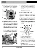
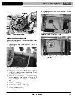
7. Insert new dies to indicator line on the dies.
See
Figure 9. Die numbers 1 through 4 on the dies must
1210 Oil-less Threading Machine
Needle Pin,
Drip Rate
Adjustment Screw
-
+
Look For
Coolant
Flow Here
Die Head
Retaining
Knob
Index Line
Link
Throwout
Lever
Clamp Lever
Washer
Head
Clamp Lever
Size Bar
Cam Plate


