


You need to complete the various fields
shown on the
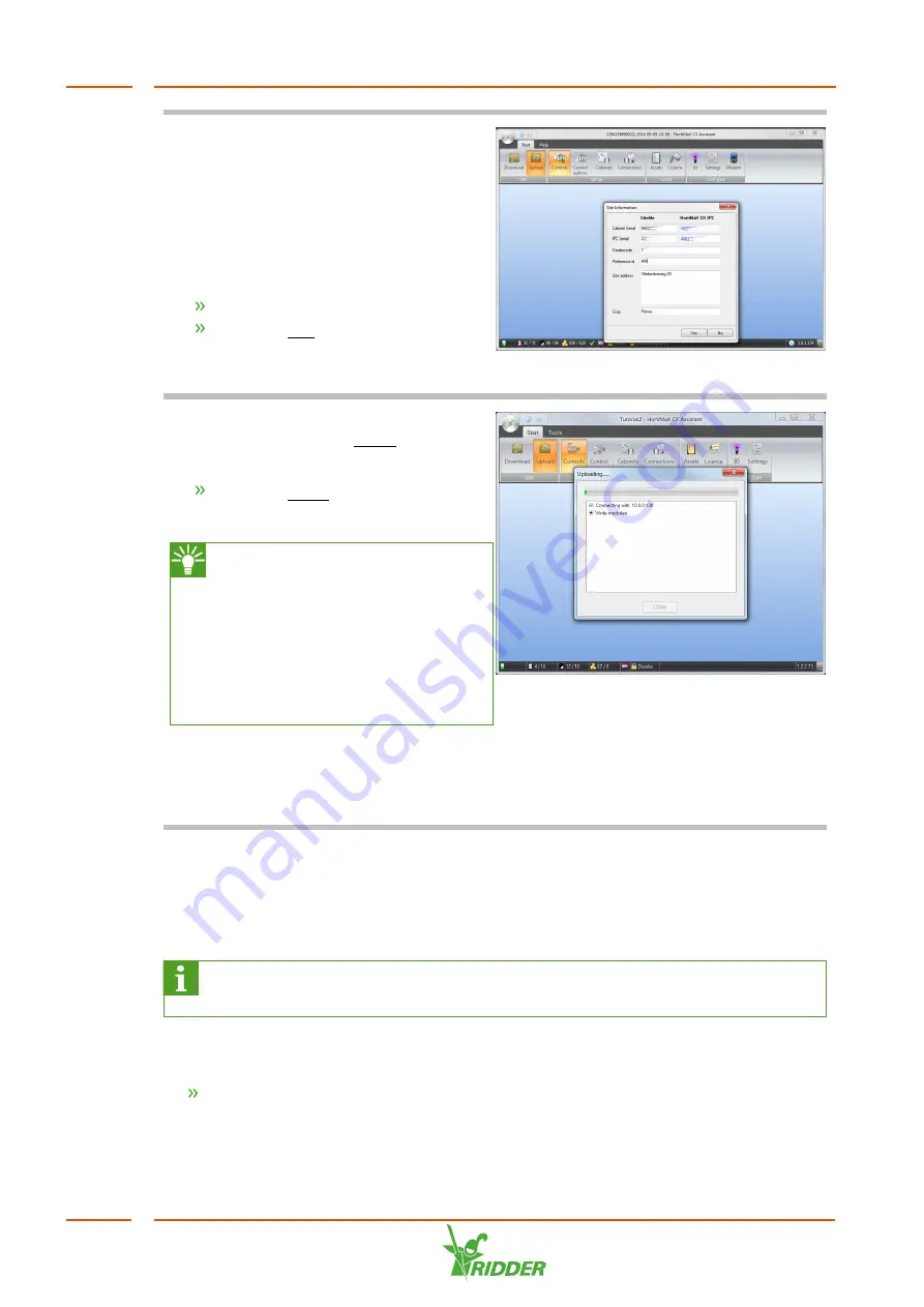
Site Information
screen.
Some information, such as the reference
ID, has been provided by Ridder Growing
Solutions.
The serial numbers are pre-entered
unless you have replaced the IPC.
Complete the fields.
Click the Yes button.
The software starts uploading the site
file.
This may take some time. Once the
upload is complete, the Close button will
be enabled.
Click the Close button.
You have uploaded the site file to the IPC.
The CX Assistant allows you to
test the I/O connections. To do
this, you need to be connected to
the IPC and you must have
uploaded the site file to the
HortiMaX CX500 on the IPC. See
the "CX Assistant tutorial” guide
for more information.
If the wiring has been connected
correctly, the process computer will start
running immediately and activate the
controls based on the default settings.
5.3
Software settings
The HortiMaX CX500 can be operated using Synopta. Synopta is the operating
interface software for the HortiJet Pro and is installed on the grower’s PC / network.
For more information on Synopta, see the "Synopta software installation
guide”.
Depending on the configuration chosen for the CX Assistant, controls will become
available for use in Synopta.
Check the controls and the associated settings in Synopta.
For more information on controls and settings, please see the Synopta help. To access
this help, use the key combination [Ctrl] + [F1].
HortiJet Pro
36