
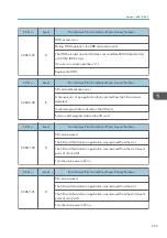

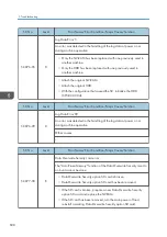


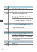
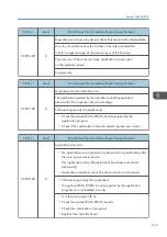

SC No.
Level
Error Name/Error Condition/Major Cause/Solution
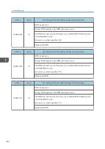
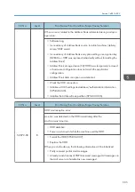
SC876-05
D
Log Data Error 5
An error was detected in the handling of the log data at power on or
during machine operation.
• Only the NV-RAM has been replaced with one previously used in
another machine.
• Only the HDD has been replaced with one previously used in
another machine.
• Attach the original NV-RAM.
• Attach the original HDD.
• With the configuration that caused the SC, initialize the HDD
(SP5-832-004).
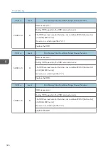
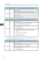
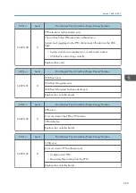
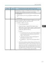
SC No.
Level
Error Name/Error Condition/Major Cause/Solution
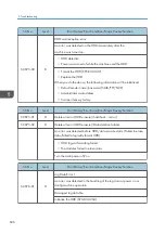
SC876-99
D
Log Data Error 99
An error was detected in the handling of the log data at power on or
during machine operation.
Other causes
-
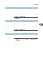
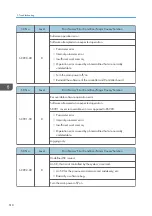
SC No.
Level
Error Name/Error Condition/Major Cause/Solution
SC877-00
B
Data Overwrite Security card error
The "Auto Erase Memory" function of the Data Overwrite Security is set to
on but it cannot be done.
• Data Overwrite Security option SD card is broken.
• Data Overwrite Security option SD card has been removed.
• If the SD card is broken, prepare a new Data Overwrite Security
option SD card and replace the NVRAM.
• If the SD card has been removed, turn the main power off and
reinstall a working Data Overwrite Security option SD card.
5. Troubleshooting
608
Summary of Contents for MET-C1
Page 1: ...Model MET C1 Machine Code D176 D177 Field Service Manual September 2013 Subject to change ...
Page 2: ......
Page 22: ...20 ...
Page 50: ...1 Product Information 48 ...
Page 57: ...4 Input the password 5 Press OK Main Machine Installation 55 ...
Page 58: ...6 Confirm the Password 7 Press OK 2 Installation 56 ...
Page 60: ...11 Confirm the password 12 Press OK 13 Cycle the power OFF ON 2 Installation 58 ...
Page 65: ...2 Remove the orange tape and retainers on the outside Main Machine Installation 63 ...
Page 72: ... When moving the machine do not press against the ADF 2 Installation 70 ...
Page 95: ...7 Upper left cover A 1 8 Left rear cover A 2 1 Bin Tray BN3110 93 ...
Page 96: ...9 Inverter tray A tray support rod cover B 1 10 Paper output cover A 1 2 Installation 94 ...
Page 102: ...3 Attach the part B to the shift tray A 4 Paper output tray A 2 Installation 100 ...
Page 104: ...9 Paper output cover A 1 10 Attach the shift tray feeler A 2 Installation 102 ...
Page 113: ...5 Upper left cover A 1 6 Left rear cover A 2 Internal Finisher SR3130 111 ...
Page 116: ...13 Upper rear inner cover A 2 14 Install a screw A removed in step 12 2 Installation 114 ...
Page 156: ...14 Re install the connecter cover 1 15 Reassemble the machine 2 Installation 154 ...
Page 167: ...18 Close the right cover Smart Card Reader Built in Unit Type M2 D739 36 165 ...
Page 220: ...3 Preventive Maintenance 218 ...
Page 227: ...2 Belt A 3 Front cover A Exterior Covers 225 ...
Page 237: ...2 Waste Toner Cover A Reverse Tray 1 Reverse Tray A Exterior Covers 235 ...
Page 244: ...3 Harness guide A 2 4 Bracket covers A B 4 Replacement and Adjustment 242 ...
Page 251: ...3 LCD panel unit A Operation Panel Unit 249 ...
Page 258: ...2 SIO unit A 2 7 3 Bracket A 4 3 4 Replacement and Adjustment 256 ...
Page 259: ...4 Spring A 5 Scanner motor unit A 2 1 6 Scanner motor A 2 Scanner Unit 257 ...
Page 284: ...3 Remove the PCDU cover A Y x 1 B M x 1 C C x 1 D K x 1 4 Replacement and Adjustment 282 ...
Page 308: ...4 Replacement and Adjustment 306 ...
Page 309: ...Fusing Entrance Sensor 1 Open the right cover page 293 Image Transfer Unit 307 ...
Page 316: ...3 ITB contact and release sensor A 4 Replacement and Adjustment 314 ...
Page 331: ...3 Hopper Y A Toner End Sensor 1 Hopper page 325 2 Toner end sensor A Drive Unit 329 ...
Page 341: ...2 Transport screw unit for K A claw 1 Drive Unit 339 ...
Page 347: ...2 Fusing lower cover A 4 Fusing Front Cover 1 Fusing unit page 340 Fusing Unit 345 ...
Page 350: ...6 Left frame A 4 4 7 Side plate A 1 4 Replacement and Adjustment 348 ...
Page 363: ...3 Harness A 1 3 4 Paper exit sensor unit A 1 1 Paper Exit 361 ...
Page 365: ...3 Reverse sensor A Reverse Motor 1 Paper exit unit page 359 2 Gear A Paper Exit 363 ...
Page 367: ...2 Fusing exit sensor unit A 1 1 1 3 Fusing exit sensor A Paper Exit 365 ...
Page 380: ...5 By pass tray A 4 3 4 4 Replacement and Adjustment 378 ...
Page 391: ...2 Harness guide A 1 3 Duplex exit sensor unit A 1 Duplex Unit 389 ...
Page 392: ...4 Duplex exit sensor A 1 4 Replacement and Adjustment 390 ...
Page 410: ...1 Power supply box page 405 2 HVP_CB A 4 1 4 Replacement and Adjustment 408 ...
Page 419: ...Power Box Cooling Fan 1 Rear cover page 230 2 Power box cooling fan A 2 Fans Filters 417 ...
Page 446: ...5 Troubleshooting 444 ...
Page 448: ...Controller self diagnosis flowchart 5 Troubleshooting 446 ...
Page 449: ...Self Diagnostic Mode 447 ...
Page 450: ...5 Troubleshooting 448 ...
Page 451: ...Self Diagnostic Mode 449 ...
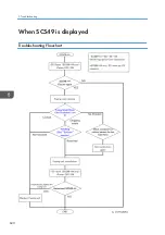
Page 622: ...When SC549 is displayed Troubleshooting Flowchart 5 Troubleshooting 620 ...
Page 628: ...When SC670 is displayed Troubleshooting Flowchart 5 Troubleshooting 626 ...
Page 629: ...Jam Detection Jam Display When a jam occurs cause positions will blink Jam Detection 627 ...
Page 630: ...Sensor Locations 5 Troubleshooting 628 ...
Page 637: ...Image Quality When an abnormal image is generated Image Quality 635 ...
Page 642: ...5 Troubleshooting 640 ...
Page 647: ...Model MET C1 Machine Code D146 D147 D148 D149 D150 Appendices 8 April 2013 ...
Page 648: ......
Page 650: ...2 ...
Page 687: ...MEMO 39 ...
Page 688: ...MEMO 40 EN ...


