
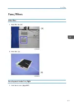
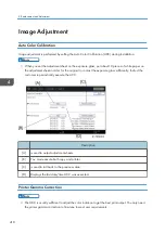


Color Registration
Adjust color registration with the following procedure when color registration errors occurred.
Check the occurrence of color registration errors
Prepare some A3 sheets.
1. Execute SP2-111-004 (Forced line Position Adj.: Mode d)
2. Make sure that execution completed successfully with using SP2-194-007 (MUSIC). If the value of
SP2-194-007 is “0”, it indicates that the result of SP2-111-004 was successful. If the value of
SP2-194-007 is “1”, it indicates that the result of SP2-111-004 was a failure, which you need to
fix the color registration errors (See “Ways to fix color registration errors” page 424).
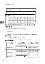
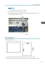
3. Execute SP2-109-003 (Test Pattern: Pattern Selection)
4. With a loupe, check the details of the color registration errors on the printed test pattern
• Specification: Main/Sub is smaller than 180.0um
• No color registration errors: Adjustment completed.
• Color registration errors occurred: Adjust the color registration errors (See “Ways to fix color
registration errors” page 424)
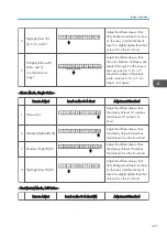
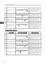
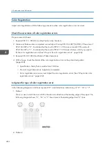
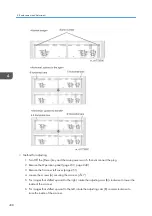
Judgment for type of color registration error
In the following diagrams, solid lines represent “K” and dotted lines indicate any of “C”, “M” or “Y”.
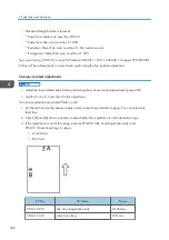
1. Pattern 1
This is a case in which there is a shift in the sub-scan direction at the leading edge of the paper. The
following diagram shows “C”, “M” or “Y” lines closer to the leading edge than “K” lines.
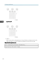
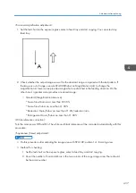
2. Pattern 2
4. Replacement and Adjustment
424
Summary of Contents for MET-C1
Page 1: ...Model MET C1 Machine Code D176 D177 Field Service Manual September 2013 Subject to change ...
Page 2: ......
Page 22: ...20 ...
Page 50: ...1 Product Information 48 ...
Page 57: ...4 Input the password 5 Press OK Main Machine Installation 55 ...
Page 58: ...6 Confirm the Password 7 Press OK 2 Installation 56 ...
Page 60: ...11 Confirm the password 12 Press OK 13 Cycle the power OFF ON 2 Installation 58 ...
Page 65: ...2 Remove the orange tape and retainers on the outside Main Machine Installation 63 ...
Page 72: ... When moving the machine do not press against the ADF 2 Installation 70 ...
Page 95: ...7 Upper left cover A 1 8 Left rear cover A 2 1 Bin Tray BN3110 93 ...
Page 96: ...9 Inverter tray A tray support rod cover B 1 10 Paper output cover A 1 2 Installation 94 ...
Page 102: ...3 Attach the part B to the shift tray A 4 Paper output tray A 2 Installation 100 ...
Page 104: ...9 Paper output cover A 1 10 Attach the shift tray feeler A 2 Installation 102 ...
Page 113: ...5 Upper left cover A 1 6 Left rear cover A 2 Internal Finisher SR3130 111 ...
Page 116: ...13 Upper rear inner cover A 2 14 Install a screw A removed in step 12 2 Installation 114 ...
Page 156: ...14 Re install the connecter cover 1 15 Reassemble the machine 2 Installation 154 ...
Page 167: ...18 Close the right cover Smart Card Reader Built in Unit Type M2 D739 36 165 ...
Page 220: ...3 Preventive Maintenance 218 ...
Page 227: ...2 Belt A 3 Front cover A Exterior Covers 225 ...
Page 237: ...2 Waste Toner Cover A Reverse Tray 1 Reverse Tray A Exterior Covers 235 ...
Page 244: ...3 Harness guide A 2 4 Bracket covers A B 4 Replacement and Adjustment 242 ...
Page 251: ...3 LCD panel unit A Operation Panel Unit 249 ...
Page 258: ...2 SIO unit A 2 7 3 Bracket A 4 3 4 Replacement and Adjustment 256 ...
Page 259: ...4 Spring A 5 Scanner motor unit A 2 1 6 Scanner motor A 2 Scanner Unit 257 ...
Page 284: ...3 Remove the PCDU cover A Y x 1 B M x 1 C C x 1 D K x 1 4 Replacement and Adjustment 282 ...
Page 308: ...4 Replacement and Adjustment 306 ...
Page 309: ...Fusing Entrance Sensor 1 Open the right cover page 293 Image Transfer Unit 307 ...
Page 316: ...3 ITB contact and release sensor A 4 Replacement and Adjustment 314 ...
Page 331: ...3 Hopper Y A Toner End Sensor 1 Hopper page 325 2 Toner end sensor A Drive Unit 329 ...
Page 341: ...2 Transport screw unit for K A claw 1 Drive Unit 339 ...
Page 347: ...2 Fusing lower cover A 4 Fusing Front Cover 1 Fusing unit page 340 Fusing Unit 345 ...
Page 350: ...6 Left frame A 4 4 7 Side plate A 1 4 Replacement and Adjustment 348 ...
Page 363: ...3 Harness A 1 3 4 Paper exit sensor unit A 1 1 Paper Exit 361 ...
Page 365: ...3 Reverse sensor A Reverse Motor 1 Paper exit unit page 359 2 Gear A Paper Exit 363 ...
Page 367: ...2 Fusing exit sensor unit A 1 1 1 3 Fusing exit sensor A Paper Exit 365 ...
Page 380: ...5 By pass tray A 4 3 4 4 Replacement and Adjustment 378 ...
Page 391: ...2 Harness guide A 1 3 Duplex exit sensor unit A 1 Duplex Unit 389 ...
Page 392: ...4 Duplex exit sensor A 1 4 Replacement and Adjustment 390 ...
Page 410: ...1 Power supply box page 405 2 HVP_CB A 4 1 4 Replacement and Adjustment 408 ...
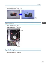
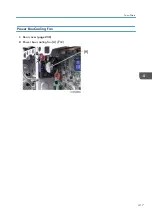
Page 419: ...Power Box Cooling Fan 1 Rear cover page 230 2 Power box cooling fan A 2 Fans Filters 417 ...
Page 446: ...5 Troubleshooting 444 ...
Page 448: ...Controller self diagnosis flowchart 5 Troubleshooting 446 ...
Page 449: ...Self Diagnostic Mode 447 ...
Page 450: ...5 Troubleshooting 448 ...
Page 451: ...Self Diagnostic Mode 449 ...
Page 622: ...When SC549 is displayed Troubleshooting Flowchart 5 Troubleshooting 620 ...
Page 628: ...When SC670 is displayed Troubleshooting Flowchart 5 Troubleshooting 626 ...
Page 629: ...Jam Detection Jam Display When a jam occurs cause positions will blink Jam Detection 627 ...
Page 630: ...Sensor Locations 5 Troubleshooting 628 ...
Page 637: ...Image Quality When an abnormal image is generated Image Quality 635 ...
Page 642: ...5 Troubleshooting 640 ...
Page 647: ...Model MET C1 Machine Code D146 D147 D148 D149 D150 Appendices 8 April 2013 ...
Page 648: ......
Page 650: ...2 ...
Page 687: ...MEMO 39 ...
Page 688: ...MEMO 40 EN ...


