background image

2.

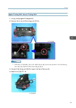
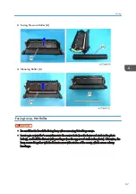
You can check the position of the hook [A] through the guide of the LED unit. Using
tweezers or a screwdriver, re-engage the hook in the correct position.

4. Replacement and Adjustment

52

Summary of Contents for Gim-MF1a

Page 1: ...Model Gim MF1a b Machine Code M172 M173 Field Service Manual September 2014...

Page 2: ......

Page 3: ...vent a fire or explosion keep the machine away from flammable liquids gases and aerosols Health Safety Conditions 1 Toner and developer is non toxic but if you get either of them in your eyes by accid...

Page 4: ...ncluding used toner and empty bottles and cartridges out of the reach of children Always store fresh toner supplies or empty bottles or cartridges in a cool dry location that is not exposed to direct...

Page 5: ...Edge Feed LEF Trademarks Adobe Acrobat PostScript PostScript 3 and Reader are either registered trademarks or trademarks of Adobe Systems Incorporated in the United States and or other countries Java...

Page 6: ...P Media Center Edition Microsoft Windows XP Tablet PC Edition The product names of Windows Vista are as follows Microsoft Windows Vista Ultimate Microsoft Windows Vista Business Microsoft Windows Vist...

Page 7: ...t Windows Server 2008 R2 Enterprise The product names of Windows Server 2012 are as follows Microsoft Windows Server 2012 Foundation Microsoft Windows Server 2012 Essentials Microsoft Windows Server 2...

Page 8: ...t Layout 13 Paper Path 14 Drive Layout 15 Machine Codes and Peripheral Configuration 16 Specifications 18 2 Installation Installation Requirements 19 Environment 19 Machine Space Requirements 20 Machi...

Page 9: ...Shutdown Method 36 Forced Shutdown 36 Exterior Covers 37 Front Cover 37 Left Cover 39 Right Cover 40 Rear Cover Rear Lower Cover 41 Upper Cover 42 Operation Panel 43 LED Optics 45 LED Unit 45 How to R...

Page 10: ...3 Paper Feed 74 Paper Feed Tray 74 Paper Feed Roller 74 Friction Pad 75 Paper End Sensor 75 By pass Feed Unit 76 By pass Feed Roller 77 By pass Friction Pad 79 By pass Paper End Sensor 80 By pass Bott...

Page 11: ...r Cover Switch 102 ADF 104 ADF Unit 104 ADF Front Cover 106 ADF Rear Cover 107 ADF Paper Feed Cover ADF Original Sensor Feeler 108 ADF Original Tray 108 ADF Original Feed Unit 109 ADF Harness Guide AD...

Page 12: ...pdate Procedure 125 Update Error Recovery Mode 129 Address Book Backup Restore 132 Back Up Restore 132 Debug Log 133 Overview 133 Operational procedure USB connection 134 Operational procedure TCP IP...

Page 13: ...173 Registration Adjustment 174 Print Area 174 Adjustment Reference Values 175 Adjustment Procedure 175 Scanner ADF Image Adjustment 175 Scanner Image Adjustment 175 ADF Image Adjustment 177 Problem...

Page 14: ...Paper Save 186 Effectiveness of Duplex Combine Function 186 1 Duplex 186 2 Combine mode 186 3 Duplex Combine 187 Recommendation 187 12...

Page 15: ...1 Product Information Product Overview Component Layout 1 Exit Switchback unit 2 Fusing unit 3 PCDU 4 LED head 5 Toner cartridge 6 By pass feed tray 7 Paper feed unit 8 Duplex paper path 13...

Page 16: ...Paper Path 1 Main machine paper feed path 2 By pass paper feed path 3 Optional tray paper feed path 4 Duplex paper feed path 1 Product Information 14...

Page 17: ...hback gear 2 Fusing drive gear 3 Drum gear 4 Registration clutch 5 Toner supply clutch 6 By pass feed clutch 7 By pass bottom plate clutch 8 Relay clutch 9 Paper feed clutch 10 Main motor 11 Duplex cl...

Page 18: ...NEW M173 M173 17 NA M173 27 EU AP M173 21 CHN NEW External Options No Item Machine Code Remarks 1 Paper Feed Unit PB1070 M440 17 NEW Paper Feed Unit PB1060 M441 17 NEW 2 Handset HS1010 M444 38 NA NEW...

Page 19: ...e SP 4500LC M903 21 NEW Photo Conductor Unit SP 4500 M906 17 NA EU AP M906 21 CHN NEW 20 000 pages 3P J Maintenance Kit SP 3600 M909 17 NA M909 27 EU AP CHN NEW ISO The number of printable pages is ba...

Page 20: ...Specifications See Appendices for the following information General Specifications Supported Paper Sizes Software Accessories Optional Equipment 1 Product Information 18...

Page 21: ...rature Range 10 C to 32 C 50 F to 89 6 F 2 Humidity Range 15 to 80 RH 3 Ambient Illumination Less than 1 500 lux do not expose to direct sunlight 4 Ventilation 3 times hr person 5 Do not install the m...

Page 22: ...Machine Dimensions Width 400 mm 15 7 inches Depth 392 mm 15 4 inches Height 406 mm 16 0 inches With Paper Feed Unit PB1060 attached 501 mm 19 7 inches With Paper Feed Unit PB1070 attached 531 mm 20 9...

Page 23: ...r supply voltage Frequency Rated current consumption NA 120 V to 127 V 60 Hz More than 10 A EU AP CHN 220 V to 240V 50 Hz 60 Hz 5 3 A 2 Permissible voltage fluctuation Destination For printing images...

Page 24: ...rd 6pin 6pin 1 Sheet Security Password 1 1 1 Sheet SEC_NOT_GW_C 1 1 1 Sheet EULA End User License Agreement 1 1 1 Cleaner Lens LED Head 1 1 1 Sheet PCDU End 4Line 1 1 1 CD ROM Page Manager 1 1 1 Guara...

Page 25: ...ng paper Operating the main power switch Removing jammed paper Providing precautions on use Connecting to computers such as configuring the port setting Giving a brief outline of the tabs in the drive...

Page 26: ...t to jolt or tip it Rough handling may cause a malfunction or damage the memory resulting in loss of stored files 1 Be sure to check the following The main power switch is turned off The power cord is...

Page 27: ...istrator Authentication under Administrator Tools 4 Enter the login password in New Password 5 Re enter the login password in Confirm Password and then click OK 6 Click OK For details see the user man...

Page 28: ...correctly programmed 4 If a proxy server is available configure the following SP settings Use Proxy SP5816 062 Set to 1 Enable Proxy server IP address SP5816 063 Proxy server Port number SP5816 064 P...

Page 29: ...he modems that support Remote 21 Answer tone detection error 22 Carrier detection error 23 Invalid setting value modem 24 Low power supply current 25 unplugged modem 26 Busy line 5 Make sure that the...

Page 30: ...modem 26 Busy line 8 Exit the SP mode SP5816 208 Error Codes Cause Code Meaning Solution Workaround Operation Error Incorrect Setting 1200 3 Attempted registration without execution of a confirmation...

Page 31: ...ations for the same mainframe Check the registration condition of the mainframe 2392 Parameter error 2393 External RCG not managed 2394 Mainframe not managed 2395 Box ID for external RCG is illegal 23...

Page 32: ...2 Installation 30...

Page 33: ...3 Preventive Maintenance Preventive Maintenance Tables See Appendices for the following information Preventive Maintenance 31...

Page 34: ...ng duplex printing Perpendicularity 0 7 mm 100 mm Linearity 0 25 mm 100 mm Parallelism In an office environment 1 0mm or less In other environments 1 5mm or less Copy Item Specification Remarks Resolu...

Page 35: ...ss Not applicable to the back of the paper when performing duplex printing Perpendicularity 1 2 mm 100 mm or less 2 4 mm 200 mm or less Missing Image Area Left 2 0 1 5 mm Right 2 0 mm Leading edge 3 0...

Page 36: ...0 mm 100 mm or less B5 SEF or more 1 5 mm 100 mm or less Less than B5 SEF Not applicable to paper fed from the by pass tray Reference value when using the by pass tray 1 0 mm 100 mm Curling after fusi...

Page 37: ...When replacing the controller board in this state not only this board it will damage other electrical components So when performing maintenance work such as replacing parts in addition to turning off...

Page 38: ...are blinking or lit current is still flowing How to start from shutdown To start the machine press the main power switch However if you press the main power switch between the beginning and the end o...

Page 39: ...Front Cover 1 Paper Feed Tray page 74 Paper Feed Tray 2 Open the by pass tray A 3 Release four hinges indicated below to detach the paper guide plate B 4 Remove the clips on the by pass tray A x2 Ext...

Page 40: ...ift the left hinge first to release while raising the by pass tray upwards The left hinge is C cut 6 Remove the screw on the front cover A in order to remove the strap that ties the front cover to the...

Page 41: ...tach the front cover A Release the left hinge B first to detach the front cover Left Cover There are five tabs on the back of the left cover Refer to the picture below 1 Open the Front Cover 2 Open th...

Page 42: ...3 Left Cover A x4 Tab x5 Right Cover There are four tabs on the back of the right cover Refer to the picture below 1 Open the Front Cover 2 Open the Rear Cover 4 Replacement and Adjustment 40...

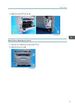
Page 43: ...3 Right Cover A x4 Tab x4 Rear Cover Rear Lower Cover 1 Two screws on Rear Lower Cover A x2 2 Open the rear cover B Exterior Covers 41...

Page 44: ...se both side hinges to detach the rear cover A 4 Rear Lower Cover A Upper Cover 1 ADF and Scanner Unit page 115 Scanner Unit with ADF 2 Operation Panel page 43 Operation Panel 4 Replacement and Adjust...

Page 45: ...wo screws on the left side of the upper cover A x2 4 Two screws on the right side of the upper cover A x2 5 Upper Cover A Operation Panel 1 Scanner Unit page 115 Scanner Unit with ADF Exterior Covers...

Page 46: ...2 Operation Panel A x 5 4 Replacement and Adjustment 44...

Page 47: ...rocedures in this section page 35 General Cautions LED Unit Be sure to clean the lens of the LED head after replacing the LED unit or if you inadvertently touch the lens when replacing another unit 1...

Page 48: ...securing screws of the front stay A x 2 5 Rotate the LED unit A in the direction of the arrow until it locks 6 Remove the spacer A ground wire B and flat cable C from the LED unit 4 Replacement and A...

Page 49: ...as if to rotate the spacer slightly 7 Slightly flex the side plates outward and pull the LED unit A out of the machine When you attach the LED unit engage the LED unit s shaft ends on the upper part w...

Page 50: ...8 Bend the stay A to release the left and right tabs and then separate the stay from the LED head B 9 Remove the two spring holders B from the LED head A 4 Replacement and Adjustment 48...

Page 51: ...How to Re engage Disengaged Springs If the spring hook A of the LED unit holder is disengaged re engage it according to the following procedure Hook disengaged A LED Optics 49...

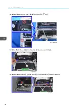
Page 52: ...e spring Right side 1 Remove the right cover and then remove the gear unit page 59 Gear Unit 2 Loosen the screws on the cover A x3 Be sure to loosen the screws holding the cover A just enough to inser...

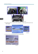
Page 53: ...tween the cover A and frame and re engage the spring hook B in the correct position Left side 1 Remove the left cover and then raise the spring using tweezers or a screwdriver inserted through the gap...

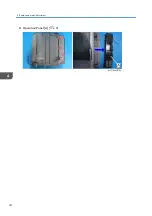
Page 54: ...2 You can check the position of the hook A through the guide of the LED unit Using tweezers or a screwdriver re engage the hook in the correct position 4 Replacement and Adjustment 52...

Page 55: ...PCDU PCDU 1 Press the release button and open the front cover A 2 Hold the grip to pull the PCDU A out PCDU 53...

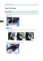
Page 56: ...h down the lever of the toner cartridge B circled in the picture below The release lever works in two steps To release the lock push down the release lever to the horizontal position 2 Hold the grip t...

Page 57: ...Image Transfer Image Transfer Roller 1 PCDU page 53 PCDU 2 Pinch both green ends of the guide A and pull it towards you 3 Image Transfer Roller A Image Transfer 55...

Page 58: ...the procedures in this section page 35 General Cautions Main Motor The main motor is located behind the drive unit 1 Drive Unit page 58 Drive Unit 2 Main Motor A x 4 x 1 Toner Supply Clutch 1 Drive Un...

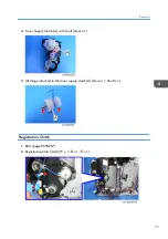
Page 59: ...Toner Supply Clutch A with shaft Gear x 1 5 All things attached to the toner supply clutch A Gear x 1 Shaft x 1 Registration Clutch 1 BCU page 95 BCU 2 Registration Clutch A x 1 x 1 x 1 Drive Unit 57...

Page 60: ...ss Guide A x 1 x 2 3 Paper Feed Clutch A x 1 Drive Unit 1 BCU page 95 BCU 2 Duplex Clutch page 62 Duplex Clutch 3 Paper Size Detection Switch page 81 Paper Size Detection Switch 4 Upper Cover page 42...

Page 61: ...Fan with Bracket A x 2 x 1 hook x 1 6 Stay A on the right side x 3 7 Drive Unit A x 8 Grounding Plate x 2 x 3 Gear Unit 1 Drive Unit page 58 Drive Unit 2 Registration Clutch page 57 Registration Clutc...

Page 62: ...age 102 Temp Humid Sensor 7 Paper Size Detection Switch page 81 Paper Size Detection Switch 8 Gear Unit A x 4 x 1 Gear x1 Before attaching the Gear Unit A close the front cover and put the tab B on th...

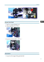
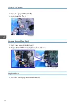
Page 63: ...By pass Feed Clutch 1 Right Cover page 40 Right Cover 2 Harness Guide A x 1 x 1 3 By pass Feed Clutch A x 1 x 1 Relay Clutch 1 By pass Feed Unit page 76 By pass Feed Unit Drive Unit 61...

Page 64: ...r Unit 3 Relay Clutch A x 1 By pass Bottom Plate Clutch 1 Right Cover page 40 Right Cover 2 By pass Bottom Plate Clutch A x 1 x 1 x 1 Duplex Clutch 1 Controller Board page 94 Controller Board 4 Replac...

Page 65: ...tch A x 1 x 1 Junction Gate Solenoid 1 Upper Cover page 42 Upper Cover 2 Controller Box page 90 Controller Box 3 One connector of the Junction Gate Solenoid A x 1 4 Junction Gate Solenoid A x 2 x 1 Dr...

Page 66: ...n off the main power switch and disconnect the power cord before you start any of the procedures in this section page 35 General Cautions Fusing Unit 1 Open the rear cover A 2 Release the lock levers...

Page 67: ...e the screws of the fusing unit x5 At the time of installation be sure to attach the pin A to the correct position If not the fusing unit cannot be attached to the main body properly 3 Separate the fu...

Page 68: ...eassemble the upper and lower fusing units with more ease by lowering the envelope lever Fusing Pressure Roller Cleaning Roller 1 Separate the fusing unit into the upper and lower fusing units page 65...

Page 69: ...attaching screws Insert a pin or jeweller s screwdriver into the service hole see the lower red circle in the photo below and hold the flat nut with your finger see the upper red circle in the photo O...

Page 70: ...1 Separate the fusing unit into the upper and lower fusing units page 65 Upper Fusing Unit Lower Fusing Unit 2 Remove the screws of the fusing lamp x3 4 Replacement and Adjustment 68...

Page 71: ...3 Two brackets A 4 Fusing lamp A 5 Hot Roller A Thermostat 1 Separate the fusing unit into the upper and lower fusing units page 65 Upper Fusing Unit Lower Fusing Unit Fusing 69...

Page 72: ...e thermistor is integrated with the drawer connector 1 Separate the fusing unit into the upper and lower fusing units page 65 Upper Fusing Unit Lower Fusing Unit 2 Hot Roller page 67 Fusing Lamp Hot R...

Page 73: ...4 Remove the bracket of the drawer connector and then remove the screws of the thermistor x3 Fusing 71...

Page 74: ...A Notes on reassembly Be sure to attach the drawer connector with its protruding part A in the position shown below Insert the flat nut A Be sure not to drop them during disassembly 4 Replacement and...

Page 75: ...Hot Roller Stripper 1 Separate the fusing unit into the upper and lower fusing units page 65 Upper Fusing Unit Lower Fusing Unit 2 Spring A 3 Hot Roller Stripper A Fusing 73...

Page 76: ...y of the procedures in this section page 35 General Cautions Paper Feed Tray 1 Pull the paper feed tray A out completely to detach it Paper Feed Roller 1 Paper Feed Tray page 74 Paper Feed Tray 2 Slid...

Page 77: ...ray page 74 Paper Feed Tray 2 Release the hooks on the bottom of the paper feed tray to detach the friction pad A Paper End Sensor 1 By pass Feed Unit page 76 By pass Feed Unit 2 PCDU page 53 PCDU 3 B...

Page 78: ...7 Front Cover 2 Left Cover page 39 Left Cover 3 Gear Unit page 59 Gear Unit 4 By pass Feed Unit A x 5 x 4 x 2 Release the hook A and then insert a flat blade screwdriver into the space B to detach the...

Page 79: ...Gear Unit page 59 Gear Unit 2 By pass Feed Unit page 76 By pass Feed Unit When attaching the By pass Feed Unit and Gear Unit secure the harness with clamps to prevent the harness from being caught by...

Page 80: ...f the by pass feed guide A x 2 Bearing x 2 4 Slide the by pass feed guide A with the by pass feed roller to the right to detach it from the machine 5 Detach the by pass feed roller with the shaft B fr...

Page 81: ...x1 By pass Friction Pad 1 By pass Feed Unit page 76 By pass Feed Unit 2 Bottom Plate A If you cannot remove the bottom plate because the part A prevents the cam B from releasing rotate the shaft C to...

Page 82: ...ressing its hinge downward x 1 By pass Paper End Sensor 1 By pass Feed Unit page 76 By pass Feed Unit 2 Bracket with By pass Sensor A x 1 3 Detach the By pass Paper End Sensor A from the bracket Hook...

Page 83: ...pass Feed Unit page 76 By pass Feed Unit 2 By pass Feed Lower Cover A x 3 3 By pass Bottom Plate HP Sensor A x 1 Hook Paper Size Detection Switch 1 Paper Feed Tray page 74 Paper Feed Tray 2 Right Cove...

Page 84: ...3 Bracket with Paper Size Detection Switch A x 2 4 Harness for Paper Size Detection Switch x 2 5 Detach the Paper Size Detection Switch A from the bracket Hook x 2 4 Replacement and Adjustment 82...

Page 85: ...on page 35 General Cautions Exit Switchback Sensor 1 Upper Cover page 42 Upper Cover 2 Exit Switchback Sensor A Hook x 1 Duplex Entrance Sensor 1 PSU page 92 PSU 2 Duplex Clutch page 62 Duplex Clutch...

Page 86: ...A Use pliers to pinch the linking part in order to separate 6 Duplex Entrance Sensor A x 1 Hook Exit Switchback Roller Duplex Exit Gear 1 Upper Cover page 42 Upper Cover 2 Junction Gate Solenoid page...

Page 87: ...3 Paper Guide A x 2 x 1 4 Release the bearing at the right end of the exit switchback roller x 1 5 Remove the E ring A on the left side of the exit switchback roller Paper Transport 85...

Page 88: ...Registration Roller Driven 1 Gear Unit page 59 Gear Unit 2 Registration Sensor page 88 Registration Sensor 3 HVPS with bracket page 98 HVPS with Bracket 4 Release the bearing A at the left end of the...

Page 89: ...remove the grounding plate A x 1 x 1 6 Insert a flathead screwdriver into the gap on the left of the registration roller guide to release the protruding part 7 Release the harness from the guide A to...

Page 90: ...rom the guide A Registration Roller Drive 1 Registration Roller Driven page 86 Registration Roller Driven 2 Slide the registration roller drive A to the right to remove it Registration Sensor 1 PCDU p...

Page 91: ...2 Sheet A 3 Release the hooks of the harness cover A with a screwdriver to remove it 4 Registration Sensor A Hook x 1 Paper Transport 89...

Page 92: ...main power switch and disconnect the power cord before you start any of the procedures in this section page 35 General Cautions Controller Box 1 Right Cover page 40 Right Cover 2 Controller Box A x 9...

Page 93: ...3 Remove the speaker connector x 1 FCU 1 Controller Box page 90 Controller Box 2 FCU A x4 x 1 Be sure not to insert the flat cable obliquely Interface Cover 1 FCU page 91 FCU Electrical Components 91...

Page 94: ...90 Controller Box 2 Speaker A x 2 PSU 1 Paper Feed Tray page 74 Paper Feed Tray 2 Left Cover page 39 Left Cover 3 Rear Cover Rear Lower Cover page 41 Rear Cover Rear Lower Cover 4 Controller Board pag...

Page 95: ...ove the screws and connectors on the left side of the PSU x 3 x 2 6 Remove the screw and connector on the right side of the PSU x 1 x 1 7 Two screws on the rear side of the PSU x 2 Electrical Componen...

Page 96: ...8 PSU A with Bracket x 1 9 Cover A x 2 10 Detach the PSU A from the bracket x 6 Controller Board 1 FCU page 91 FCU 2 Controller Board A M172 Single sided ADF model 4 Replacement and Adjustment 94...

Page 97: ...x 4 x 10 M173 Single Pass ADF model x 4 x 11 BCU 1 Controller Board page 94 Controller Board Electrical Components 95...

Page 98: ...d on the BCU board 4 Install the new BCU in the machine 5 Enter the machine s serial number into the BCU SP5 811 004 If the machine s serial number is not entered correctly into the new BCU SC995 01 s...

Page 99: ...d However DO NOT turn off the main power switch Continue with this procedure 5 Enter the machine serial number SP5 811 001 For information on how to configure SP5 811 001 contact your supervisor or su...

Page 100: ...2 Toner End Sensor A x 1 x 1 Tab x 1 HVPS 1 Left Cover page 39 Left Cover 2 HVPS A x 4 x 2 Tab x 2 HVPS with Bracket 1 Left Cover page 39 Left Cover 4 Replacement and Adjustment 98...

Page 101: ...Fan 1 Left Cover page 39 Left Cover 2 Fusing Fan A x 2 x 1 x 2 When you reattach the Fusing Fan attach it correctly as shown above the face of the fan with the sticker is on the outside PCDU Cooling...

Page 102: ...sticker must be on the inside PSU Cooling Fan 1 Left Cover page 39 Left Cover 2 PSU Cooling Fan A x 2 x 1 x 2 When you reattach the PSU cooling fan the face of the fan with the sticker must be on the...

Page 103: ...DC Switch A with Bracket x 2 3 Detach the DC Switch from the bracket A x 1 Front Door Interlock Switch 1 Left Cover page 39 Left Cover 2 Front Door Interlock Switch A x 1 x 2 Electrical Components 10...

Page 104: ...er page 39 Left Cover 2 Rear Door Interlock Switch A x 1 x 2 Temp Humid Sensor 1 Right Cover page 40 Right Cover 2 Temp Humid Sensor A x 1 x 1 Rear Cover Switch 1 Controller Board page 94 Controller B...

Page 105: ...2 Rear Cover Switch A x 1 Hook Electrical Components 103...

Page 106: ...edures in this section page 35 General Cautions ADF Unit 1 Right Cover page 40 Right Cover 2 Controller Box page 90 Controller Box 3 Disconnect the cables for the ADF Unit M172 Single sided ADF model...

Page 107: ...5 Disconnect the cables for the ADF Unit x1 6 Scanner Rear Cover A x2 7 Disconnect and pull out the cable from the Scanner Rear Cover A ADF 105...

Page 108: ...s on the hinge on the right side of the ADF x2 9 Lift the ADF A to detach Tip back the ADF and lift it vertically to detach it ADF Front Cover 1 Three screws on the ADF Front Cover A x3 4 Replacement...

Page 109: ...2 Open the ADF Paper Feed Cover A and then detach the ADF Front Cover B ADF Rear Cover 1 Open the ADF Paper Feed Cover A 2 ADF Original Tray page 108 ADF Original Tray 3 ADF Rear Cover A x2 ADF 107...

Page 110: ...1 ADF Rear Cover page 107 ADF Rear Cover 2 Slide the ADF Paper Feed Cover A to detach 3 Separate the ADF Original Sensor Feeler B from the ADF Paper Feed Cover A ADF Original Tray 1 Open the ADF Pape...

Page 111: ...ease both side hinges to detach the ADF Original Tray A ADF Original Feed Unit 1 ADF Front Cover page 106 ADF Front Cover 2 Pull up the push lever vertically and remove the ADF Original Feed Unit A AD...

Page 112: ...l Feed Unit 3 ADF Harness Guide A x2 x2 4 Release the tabs on the back of the ADF Harness Guide A and then remove the ADF Original Set Sensor B and ADF Paper Feed Cover Open Closed Sensor C ADF Transp...

Page 113: ...DF Drive Unit A x3 3 Remove the Harness B from the ADF Transport Motor and ADF Gear Unit A ADF Transport Unit 1 ADF Drive Unit page 110 ADF Transport Motor ADF Gear Unit 2 ADF Transport Unit A x2 ADF...

Page 114: ...ADF Separation Roller ADF Separation Roller Cover 1 ADF Transport Unit page 111 ADF Transport Unit 2 ADF Separation Roller Cover A 3 ADF Separation Roller A 4 Replacement and Adjustment 112...

Page 115: ...ADF Paper Exit Guide 1 ADF Transport Unit page 111 ADF Transport Unit 2 ADF Paper Exit Guide A ADF Pre Scanning Roller ADF Pre Scanning Shaft 1 ADF Unit page 104 ADF Unit ADF 113...

Page 116: ...2 Remove the Plate A and then separate the ADF Pre Scanning Roller B and ADF Pre Scanning Shaft C x3 Attach the pressurized spring A to the plate when reassembling 4 Replacement and Adjustment 114...

Page 117: ...5 General Cautions Scanner Unit with ADF When you want to detach only the ADF see ADF Unit page 104 ADF Unit 1 Right Cover page 40 Right Cover 2 Controller Box page 90 Controller Box 3 Disconnect the...

Page 118: ...39 Left Cover 5 Disconnect the cables for the Scanner Unit ADF Unit and Operation Panel x1 6 Scanner Rear Cover A x1 7 Disconnect and pull out the cable from the Scanner Rear Cover A 4 Replacement an...

Page 119: ...or the Scanner Unit x4 9 Lift the Scanner Unit A to detach from the machine Make sure that the cable is not caught during removal Disconnect the cable A of the Operation Panel from the fastener hook i...

Page 120: ...Scanner unit only 1 ADF page 104 ADF Unit 2 Disconnect the cables for the Scanner Unit and Operation Panel x4 4 Replacement and Adjustment 118...

Page 121: ...or the Scanner Unit x4 4 Lift the Scanner Unit A to detach from the machine Make sure that the cable is not caught during removal Disconnect the cable A of the Operation Panel from the fastener hook i...

Page 122: ...5 Operation Panel page 43 Operation Panel 4 Replacement and Adjustment 120...

Page 123: ...s 8 Printer SP Tables Scanner SP Tables Enabling and Disabling Service Program Mode Do not let the user access the SP mode Only service representatives are allowed to access the SP mode The machine qu...

Page 124: ...ervice mode Types of SP Modes Type Description 1 System SP SP modes related to the controller engine functions 2 Fax SP SP modes related to the fax functions 3 Printer SP SP modes related to the print...

Page 125: ...Service Program Mode 123...

Page 126: ...s 8 x64 Windows 8 1 Windows 8 1 x64 Windows Server 2003 Windows Server 2003 x64 Windows Server 2003 R2 Windows Server 2003 R2 x64 Windows Server 2008 Windows Server 2008 x64 Windows Server 2008 R2 Win...

Page 127: ...tures check box of SmartDeviceMonitor for Client Check the engine boot version to update If an update is executed with wrong boot version and when a recovery firmware update is executed the screen fre...

Page 128: ...ning on the computer The printer restarts automatically when the update process is complete Never turn the printer off during updates 1 Launch the controller firmware update tool 2 Select a language a...

Page 129: ...system version for Update data is later than the system version for Printer and then click Next The following screen is an example The versions that actually appear may be different 6 Click OK Do not...

Page 130: ...and on automatically 9 Check that the new firmware version is displayed using the control panel of the printer 10 Check the firmware version displayed in the first line User Tools key System Settings...

Page 131: ...eceived data Decompressing the data 11 Rewriting ROM Rewriting ROM 15 Checking ROM Verifying 17 Completing the update Completing the update Firmware update completed Update Error Recovery Mode If the...

Page 132: ...check error Verifying Recovery Mode You can launch the recovery mode to update data via USB connection by turning off and then back on the main power under the following conditions If the update is s...

Page 133: ...us Progress Data In LED Flashing Updating Data In LED Lit Update complete Alert LED Lit Error Alert LED Flashing Recovery mode activates due to failure of the engine firmware update Updating the Firmw...

Page 134: ...Address Book Backup Restore Back Up Restore This is to be done by the user For details see the user manual Connecting the Machine System Settings 5 System Maintenance 132...

Page 135: ...he compatible OSs are shown below Windows XP Windows Vista Windows 7 Windows 8 32bit Yes Yes Yes Yes 64bit Yes Yes Yes See the note below Note Windows certification is necessary for Windows 8 64 bit w...

Page 136: ...en reboot the machine The initial factory value is 1 disabled 2 The dbgmon driver install wizard is launched Follow the instruction to install the driver The driver install wizard is not launched if d...

Page 137: ...machine s IP address 1 You can connect the machine and computer via TCP IP by launching dbgmon with the option of 1 machine s ip address 2 You can retrieve the log with the same procedure as that spec...

Page 138: ...ting the oldest log If the USB memory stick is removed and reinserted a new date based directory is created and the log files are created inside the directory When a USB memory stick is used as USB lo...

Page 139: ...l settings of the copy engine to take effect and then starts an independent self diagnostic test program The self diagnostic test checks the CPU memory and so on An SC code is displayed if the self di...

Page 140: ...en on resets SCs displayed on the operation panel These are re displayed if the error occurs again Turn the main power switch off and on When a Level D SC code occurs When a Level D SC occurs a screen...

Page 141: ...scanner has scanned the white plate but cannot detect the certain white level Defective exposure lamp Defective exposure lamp stabilizer Defective power source harness Defective signal harness High v...

Page 142: ...LED Optics SC No Level Error Name Error Condition Major Cause Solution SC230 00 D FGATE 1 Does not turn ON GPIO 2 has not been asserted although the specified time 200 ms elapsed after setting JOB to...

Page 143: ...tive Harness disconnection Turn the main power OFF and then ON 1 FGATE Signals used between the controller and the engine in order to send the information about the sub scan length of the page to be p...

Page 144: ...the main power OFF and then ON Replace the LED head SC300 Image Processing 1 SC No Level Error Name Error Condition Major Cause Solution SC302 D High voltage output error Charge unit Development unit...

Page 145: ...r defective light leak Supplying pick does not engage Defective Supplying clutch Defective Drive mechanism of screw for supplying toner cartridge Turn the main power OFF and then ON SC No Level Error...

Page 146: ...ace the controller board Check the connector connection SC No Level Error Name Error Condition Major Cause Solution SC498 00 C Temperature humidity Sensor error Temperature sensor output error Out of...

Page 147: ...ed or other error By pass bottom plate sensor feeler stuck or other error Check and replace the by pass bottom plate sensor connector connection Replace the by pass bottom plate sensor feeler Replace...

Page 148: ...an motor Check the connector Replace the harness Replace the IOB SC No Level Error Name Error Condition Major Cause Solution SC531 00 D Development Cooling fan error The fan motor lock rotating state...

Page 149: ...rness disconnection Defective IOB Replace the fan motor Check the connector Replace the harness Replace the IOB SC No Level Error Name Error Condition Major Cause Solution SC541 00 A Broken fusing Cen...

Page 150: ...2 The heater Center thermistor does not reach the reload temperature 50 seconds after the start of motor rotation Fusing lamp disconnected The overtemperature prevention mechanism started working Cle...

Page 151: ...ftware or temperature sensor error Clear the SP fusing SC Replace the PSU Replace the Engine Board Replace the fusing thermopile Replace the Fusing Unit SC No Level Error Name Error Condition Major Ca...

Page 152: ...st does not occur when the fusing relay is in an ON state an error results Damaged fusing relay open contact Failed fusing relay drive circuit PSU fuse 24VS blown Turn the main power OFF and then ON R...

Page 153: ...or Cause Solution SC553 01 SC553 02 A Fusing End thermistor high temperature detected software 553 01 In a condition of 235 degrees C or higher temperature the temperature has increased more than 10 d...

Page 154: ...rror Clear the SP fusing SC Replace the PSU Replace the Engine Board Replace the fusing thermopile Replace the Fusing Unit SC No Level Error Name Error Condition Major Cause Solution SC557 00 C Zero c...

Page 155: ...ngine board is faulty Engine board software defective Check the connection between the controller board and engine board Turn the main power off on SC No Level Error Name Error Condition Major Cause S...

Page 156: ...ng EEPROM Close 669 11 ID error during EEPROM data write 669 12 Channel error during EEPROM data write 669 13 Device error during EEPROM data write 669 14 Communication interrupted error during EEPROM...

Page 157: ...U SC No Level Error Name Error Condition Major Cause Solution SC669 36 D EEPROM communication error The EEPROM data has been transferred to the SRAM twice in succession but the two sets of transferred...

Page 158: ...g to the energy saver mode after the engine automatically goes off and rebooting the machine The engine board does not start up The connection between the controller board and engine board is faulty C...

Page 159: ...M SRAM OPEN Verification error Turn the main power OFF and then ON Replace the toner cartridge ID chip SC No Level Error Name Error Condition Major Cause Solution SC682 D Device ID is not identified P...

Page 160: ...the power is turned ON the number of mounted paper tray units is detected and the number exceeds three The number of mounted paper tray units exceeds the specifications Reduce the number of mounted p...

Page 161: ...6 13 D open error SC816 14 D Memory address error SC816 15 D open error SC816 16 D open error SC816 17 D open error SC816 18 D open error SC816 19 D Double open error SC816 20 D open error SC816 22 D...

Page 162: ...on for transition to STR Turn the main power off on Replace the controller board SC No Level Error Name Error Condition Major Cause Solution SC818 00 D Watchdog timer error The system program fell int...

Page 163: ...nc input timeout After the PRREQ signal is detected the FSYNC FGATE signal of the first color is not detected even after the specified time has elapsed Connector harness defective FGATE control error...

Page 164: ...ment failure Wireless LAN board error wireless LAN card 802 11 is covered Defective wireless LAN board Loose connection Turn the main power off on Replace wireless LAN board SC No Level Error Name Err...

Page 165: ...e for storing the Address Book is unusable SC870 09 B Address Book data error Machine configuration Inconsistency in the NVRAM area used for storing settings required for Address Book configuration SC...

Page 166: ...rom cache When an error related to the Address Book is detected during startup or operation Software bug Inconsistency of Address Book source location machine delivery server LDAP server Inconsistency...

Page 167: ...T have not yet been processed Install an NVRAM device designed specifically for the model SC No Level Error Name Error Condition Major Cause Solution SC920 B Printer application error A serious applic...

Page 168: ...ition Major Cause Solution SC991 00 C Software continuity error The software has attempted to perform an unexpected operation However the process can continue running if recovery processing is carried...

Page 169: ...BCU boards Turn the main power switch off and on SC No Level Error Name Error Condition Major Cause Solution SC997 00 B Application function selection error The application has not responded to the se...

Page 170: ...y Even if they are started all applications have become unable to be rendered due to an unknown defect Software bug An option required by the application RAM DIMM board is not installed properly Turn...

Page 171: ...s internal components get very hot For this reason take care when removing misfed paper Not doing so could result in burns When removing paper misfeeds do not turn off the power If you do machine s se...

Page 172: ...des and Position Codes Jam code Shows the cause of a jam Appears in the log data Position code Shows the location of a jam Appears on the operation panel These are lists of jam codes for the main mach...

Page 173: ...iginal length error P 100 Motor defective P 1 Initial jam P Main Machine Jam Code Jam Type Position Code 1 Registration Sensor Jam B 1 Exit Switchback Sensor Jam B Z1 1 Duplex Entrance Sensor Jam Z1 Z...

Page 174: ...Jam Z1 66 Duplex Entrance Sensor Lag Jam Z1 Z2 Optional Bank Jam Code Jam Type Position Code 4 Tray 2 No Paper Feeding Y1 53 Tray 2 Relay Sensor Vertical Transport Sensor Lag Jam A1 Y1 1 Tray 2 Relay...

Page 175: ...ration Press OK 4 Select Print Test Sheet Press OK 5 Select the tray you want to adjust Press OK 6 Press Print 7 Print the test sheet to preview the settings Use this sheet to check the current print...

Page 176: ...in width of the image with SP2 103 001 004 Leading edge 2 7 to 9 9 mm Default 3 0 mm Trailing edge 0 0 to 9 9 mm Default 2 0 mm Left 0 0 to 9 9 mm Default 2 0 mm Right 0 0 to 9 9 mm Default 2 0 mm Reg...

Page 177: ...re 1 Print the test sheet page 173 Test Sheet Printing Print the test sheet and then adjust the leading edge registration in the SP mode to the optimum value 2 Do SP1 002 001 002 003 006 to check and...

Page 178: ...eet on the exposure glass and make a copy from one of the paper feed trays 2 Check the leading edge and side to side registration and adjust as necessary with the following SP modes Specification A 0...

Page 179: ...e appropriate SP modes as follows Allowable Misregistration 4 2 2 mm Leading edge 2 1 mm Left right SP No Name Range SP6 006 001 ADF Adj Regist Side to Side Front 3 0 mm SP6 006 003 ADF Adj Regist L E...

Page 180: ...blems with the printed result other than black or white dots 29 9mm Charge roller 37 7mm Registration roller 45 8mm Image transfer roller 112mm Fusing pressure roller 94mm Fusing roller 100 5mm Paper...

Page 181: ...ductor idles for 30 seconds for black and white vertical banding Effectively Prevented Problems Level 1 Pieces of white banding for half tone or continuous printing Level 2 White vertical banding for...

Page 182: ...Check that the black spots do not appear any more The effectiveness of the fusing cleaning varies depending on the types of images printed or paper types used until now Therefore the problem may be i...

Page 183: ...per frequently You can also configure Curl Prevention in the UP mode User Tools key System Settings Maintenance Curl Prevention If you set Curl Prevention to Active the machine idles for 20 seconds be...

Page 184: ...6 Troubleshooting 182...

Page 185: ...ll be different For example if the timers are all set to 60 min the grey area will disappear and no energy is saved before 60 min expires Sleep Mode Setting Sleep Mode User Tools key System Settings T...

Page 186: ...ode immediately after exiting Energy Saver mode Default Immediate Immediate The printer resumes Sleep mode immediately after printing regardless of the Sleep Mode Timer settings After Time Set by Tmr...

Page 187: ...mum value the machine will not begin saving energy until 60 minutes has expired after the last job This means that after the customer has finished using the machine for the day energy will be consumed...

Page 188: ...e Effectiveness of Duplex Combine Function Duplexing and the combine functions reduce the amount of paper used 1 Duplex Reduce paper volume in half 2 Combine mode Reduce paper volume in half 7 Energy...

Page 189: ...the duplex counter goes up by 1 For a duplex job of a three page original the duplex counter will only increase by 1 even though two sheets are used Recommendation Please explain the above features t...

Page 190: ...iously The following table shows paper savings and how the counters increase for some simple examples of duplex combine jobs 2 in 1 mode Originals Simplex Sheet used Duplex Sheets used Paper Saved Tot...

Page 191: ...Originals Simplex Sheet used Duplex Sheets used Paper Saved Total counter SP8 581 001 5 5 2 3 3 6 6 2 4 3 7 7 2 5 4 8 8 2 6 4 9 9 3 6 5 10 10 3 7 5 11 11 3 8 6 12 12 3 9 6 Paper Save 189...

Page 192: ...MEMO 190...

Page 193: ...MEMO 191...

Page 194: ...MEMO 192 EN...

Page 195: ...Model Gim MF1a b Machine Code M172 M173 Appendices September 2014...

Page 196: ......

Page 197: ...Equipment 16 Paper Feed Unit PB1060 16 Paper Feed Unit PB1070 16 2 Appendices Preventive Maintenance Tables Preventive Maintenance Tables 19 Maintenance Tables 19 Mainframe 19 Paper Feed Tray PB1060 P...

Page 198: ...XXX Data Log 77 Main SP Tables 8 83 SP8 XXX Data Log 2 83 Keys and abbreviations in Data Log 2 83 Input and Output Check 90 Input Check Table 90 Output Check Table 91 Printer Service Mode 93 SP1 XXX...

Page 199: ...em through CCD Warm up Time 19 seconds or less 23 C rated voltage First Print Time 6 5 seconds or less First Copy Time 13 5 seconds or less Continuous Copy Speed One sided copy 30 cpm A4 SEF 31 cpm LT...

Page 200: ...A6 SEF LG SEF Government LG SEF G LT SEF LT SEF HLT Executive SEF F SEF Foolscap SEF Folio SEF 16K SEF Com10 SEF Monarch SEF C5 SEF C6 SEF DL Env SEF Custom size Min 60mm x 127mm 2 4 x 5 0 Max 216mm x...

Page 201: ...io Zoom 25 400 by 1 step Resolution Scan Exposure Glass 300 600dpi ADF 300 300dpi Resolution Print 1200dpi Tone 256 tones Paper Feed Capacity Max 850 sheets Standard 250 sheets Main 100 sheets Bypass...

Page 202: ...stscript3 Interface Standard Ethernet 100BASE TX 10BASE T USB2 0 Option IEEE 802 11b g n wireless LAN interface Protocol TCP IP IPv4 IPv6 SNMP MIB WSM Compatible OS Standard Windows XP Vista 7 8 8 1 W...

Page 203: ...Scan to Email 100dpi 200dpi 300dpi 400dpi 600dpi Scan to Folder 100dpi 200dpi 300dpi 400dpi 600dpi Network TWAIN scanner When using the Exposure glass 100 600 dpi When using the ADF 100 600 dpi WIA s...

Page 204: ...257 N N N N A4 SEF 210 297 A A D C A4 LEF 297 210 N N N N B5 SEF 182 257 B B D N B5 LEF 257 182 N N N N A5 SEF 148 210 A A D N A5 LEF 210 148 B B D N B6 SEF 128 182 B B D N B6 LEF 182 128 N N D N A6...

Page 205: ...N Executive SEF 7 1 4 10 1 2 B B D N Executive LEF 10 1 2 7 1 4 N N N N F SEF 8 13 B B D C F LEF 13 8 N N N N Foolscap SEF 8 1 2 13 B B D C Foolscap LEF 13 8 1 2 N N N N Folio SEF 8 1 4 13 B B D C Fo...

Page 206: ...card SEF 100 148 N N N N Postcard LEF 148 100 N N N N Double postcard SEF 200 148 N N N N Double postcard LEF 148 200 N N N N Remarks Standard Tray Optional Tray A Supported size Need to set the dial...

Page 207: ...0 297 N B4 SEF 257 364 N B4 LEF 364 257 N A4 SEF 210 297 C A4 LEF 297 210 N B5 SEF 182 257 C B5 LEF 257 182 N A5 SEF 148 210 C A5 LEF 210 148 C B6 SEF 128 182 C B6 LEF 182 128 N A6 SEF 105 148 C A6 LE...

Page 208: ...1 2 N Executive SEF 7 1 4 10 1 2 C Executive LEF 10 1 2 7 1 4 N F SEF 8 13 C F LEF 13 8 N Foolscap SEF 8 1 2 13 C Foolscap LEF 13 8 1 2 N Folio SEF 8 1 4 13 C Folio LEF 13 8 1 4 N Com10 SEF 4 1 8 9 1...

Page 209: ...6K SEF 195 267 C 16K LEF 267 195 N Custom Size Width mm 60 216 Custom Size Length mm 127 900 Postcard SEF 100 148 C Postcard LEF 148 100 N Double postcard SEF 200 148 C Double postcard LEF 148 200 C R...

Page 210: ...OSX 10 6 8 or later PCL 5e 6 Yes Yes Yes No PostScript3 Yes Yes Yes Yes Scanner and LAN Fax drivers Driver Windows XP Windows Vista Windows 7 Windows 8 8 1 TWAIN Yes Yes Yes Yes PC FAX Yes Yes Yes Ye...

Page 211: ...nt A printer management utility for client users A utility for peer to peer printing over a NetBEUI or TCP IP network A peer to peer print utility over a TCP IP network This provides the parallel prin...

Page 212: ...er Output Capacity 250 sheet Power Consumption 15 0 W Dimension W x D x H W370 D392 H95 mm W14 6 D15 4 H3 7 inch Weight 4 1 kg 9 0 lbs Paper Feed Unit PB1070 Category Item Unit Paper Size A4 B5 A5 B6...

Page 213: ...Category Item Unit Dimension W x D x H W370 D392 H125 mm W14 6 D15 4 H4 9 inch Weight 4 5 kg 9 9 lbs Optional Equipment 17...

Page 214: ...1 Appendices Specifications 18...

Page 215: ...l keys C Clean R Replace Mainframe Paper Feed Item 20K 120K 600K EM Remarks Registration Roller C Wipe with a damp cloth Registration Sensor C Remove dust with a dry cloth when sensor failure occurs V...

Page 216: ...orm this concurrently with PCDU replacement Use the LED lens cleaner packed with the unit or mainframe Transfer Item 20K 120K 600K EM Remarks Image Transfer Roller R C Wipe with a damp cloth then dry...

Page 217: ...h a damp cloth Pull out roller Pre scanning roller Exit roller C Wipe with a damp cloth Platen R C Wipe with a dry cloth Separation roller C Wipe with a dry cloth White reference board Front surface R...

Page 218: ...les have a target yield However the total copy print volume made by the machine will not reach the target yield within the machine s targeted lifetime if the machine is used under the target usage con...

Page 219: ...ep The setting can be adjusted in the range 9 value reset to 3 0 after an NVRAM reset and the value can be changed in 0 1 mm steps with each key press DFU Denotes Design or Factory Use Do not change t...

Page 220: ...er 1 001 001 By pass E 4 0 to 4 0 0 0 0 1 mm step 1 001 002 Tray 1 E 1 001 003 Tray 2 E 1 001 006 Duplex E 1002 User S to S Reg Adjusts the printing side to side registration from each paper feed stat...

Page 221: ...en the amount of time that the paper pauses at the nip of the registration rollers if you notice a large amount of skew in printouts 1 003 011 By pass Plain E 5 to 5 0 1 mm step 1 003 012 By pass Thic...

Page 222: ...0 to 205 177 1deg step 1 105 025 C Thick1 LowTemp E 140 to 205 185 1deg step 1 105 031 FuserOffMode E 0 or 1 1 1 step The switch that turns the fuser off after the idle process runs over 30 minutes 11...

Page 223: ...or 1 0 1 1113 Env Fus Cond 1 113 001 PrePrtRotTime E 500 to 60000 7000 500msec step 1135 Inrush Control Enables or disables the setting of Inrush control 0 Disabled 1 Enabled 1 135 001 Inrush control...

Page 224: ...0 to 10 0 1mm step Adjusts the reverse stop timing of the range from the Registration Sensor Off to the Paper Exit Inverter motor Makes it slower or faster than the default 1 907 015 Re Feed Stop Posi...

Page 225: ...r 1 921 023 Tray1 Envelope E 4 0 to 4 0 0 0 0 1mm step Adds on to the adjusted values of the Plain paper 1 921 031 Tray2 Plain E 4 0 to 4 0 0 0 0 1mm step Reflects adjustment values with no change 1 9...

Page 226: ...2 Fan Off Mode Time 1 952 001 E 0 to 60 13 1min step 1998 Print Target Temp 1 998 001 Fusing Clean Temp E 140 to 205 165 1 deg step 1998 Reserve SP 1 998 002 reserve02 E 0 to 255 0 1 step 1 998 003 re...

Page 227: ...s the target dark potential Vd in the Env Division low humidity This setting is available when the bias control is On 2 001 012 Vd_ref_midhumi E 700 to 400 470 10V step Displays or adjusts the target...

Page 228: ...2 E 0 0 to 10 0 5 0 0 1 step Displays and adjusts the coefficient a2 that is of the C caluculated function F Vd AH D This setting is available when the bias control is On 2 001 103 F Coefficient a3 E...

Page 229: ...idth E 2 103 008 Duplex RightWidth E 2104 Exposure energy 2 104 010 Normal Print E 0 23 to 0 98 0 50 0 01 uJ cm2 step LEDA light emission energy Normal printing Bk Display Setting 2 104 011 Normal Dis...

Page 230: ...mm step 2 201 013 Line3 L3 E 2000000 to 2950000 3000000 50000mm step 2 201 014 Line4 L4 E 3000000 to 7950000 5000000 50000mm step 2 201 015 Line5 L5 E 8000000 to 19950000 8000000 50000mm step 2 201 01...

Page 231: ...009 Power Error E 0 or 1 0 1 step 2301 T bias Control Transfer Bias Control Use these SP s to adjust the power output and power coefficient used to transfer the toner image from drum to paper Four sep...

Page 232: ...f 30K and 60K 2 301 103 Used Adjust A4 E 0 to 100 65 1 step Output adjustment for the value of the transfer output table which is to be a basis when the transfer paper count is in the range of 60K and...

Page 233: ...tep 2 924 005 Remaining M 182 E 0 01 to 1 00 0 21 0 01g sec step 2 924 006 Remaining L 182 E 0 01 to 1 00 0 17 0 01g sec step 2925 Toner Supply 2 925 001 consumed amount E 0 0 to 100000 0 0 0 0 1mg st...

Page 234: ...ient E 0 0 to 5 0 1 5 0 1 step Coefficient for calcurating the amount of toner supplying during printing after toner cartridge is replaced 2 927 004 Initial Flag E 0 or 1 0 1 step Information used to...

Page 235: ...70 18 1count step Counter for judging the upper limit when toner remaining in the developer detected 2 930 008 MM 240 Lower E 0 to 70 34 1count step Counter for judging the lower limit when toner rema...

Page 236: ...toner remaining in the developer detected 2 930 017 Sensor Standard V E 0 0 to 3 3 2 0 0 1V step Threshold for judging the detection result of toner end sensor 2 930 018 Average Count E 0 to 255 0 1c...

Page 237: ...0 0 0 1g step Counter for detecting toner end 2 940 002 Remaining Time E 0 to 300 0 1sec step Threshold for detecting toner end 2941 Remain Control Counter for supplying triggered by the front cover o...

Page 238: ...0000 to 960000000 10490000 10000mm step The parameter which is used to calculate the print stop end threshold mm Print stop end threshold mm End threshold distance mm End margin distance mm 1 kp 65000...

Page 239: ...2 998 004 T NormalRotation2 E 1 to 100 120 1msec step Adjusts the normal rotation time of PCU reverse rotation Main SP Tables 2 43...

Page 240: ...Bias Control Development Bias Control On Off designation 3 501 001 On Off E 0 or 1 1 1 step 0 Off 1 On 3502 C Bias Control C bias Control On Off designation 3 502 001 On Off E 0 or 1 1 1 step 0 Off 1...

Page 241: ...ading and trailing edges sub scan and right and left edge main scan Do not adjust unless the customer desires a scanner margin greater than the printer margin These settings are adjusted to erase shad...

Page 242: ...to 10 0 1 step Displays the scanning level value adjustment for the red signal in Book Scan 4 609 002 Front DF Scan C 10 to 10 0 1 step Displays the scanning level value adjustment for the red signal...

Page 243: ...anning an image with the DF Adjusts the density level if the ID of outputs made in the DF and Platen mode is different 4 688 001 Front C 10 to 10 0 1 step 4 688 002 Back C 10 to 10 0 1 step 4701 CIS A...

Page 244: ...Exit This SP is done before shipping the machine to another location Turning the machine power off on also returns the exposure lamp to its home position 4 806 001 C Execute 4999 Force Simplex 4 999 0...

Page 245: ...ounting counter is displayed on the LCD or not SP5 801 001 003 will not clear this SP The value will be under an exclusive control because the value varies in segments 5 045 001 Counter Method C 0 or...

Page 246: ...083 Led Switch Specifies whether the alert LED is lit or not when toner near end condition is detected This does not change the toner near end condition indication in the operation panel LCD 5 083 001...

Page 247: ...tects toner end 0 Off 1 On 5 507 006 WasteTonerBottle C 0 or 1 1 1 step 0 Off 1 On 5 507 080 Toner Call Timing C 0 or 1 0 1 step 0 At replacement 1 AtLessThanThresh Changes the timing of the Toner Sup...

Page 248: ...controller keeps to the initial value with certain exceptions The engine SP clear SP5 801 002 is not executed 5 801 002 Engine E 0 or 1 0 1 step Initializes all registration settings for the engine an...

Page 249: ...en setting CSS for remote access only 5816 Remote Service 5 816 002 CE Call C 0 or 1 0 1 step 0 Start of the service 1 End of the service Performs the CE Call at the start or end of the service Note T...

Page 250: ...tion can not be performed If SP5 515 006 is disabled 5 816 005 Device Info C Execute Performs a call for notifying equipment internal information to the call center The call for checking equipment sta...

Page 251: ...ing connection when the connection to the G W failed 5 816 031 HTTP Retry C 0 to 255 3 1 step The number of times of retrying connection when the connection to the G W failed When the connection fails...

Page 252: ...ff 0 1 step Displays the notifying date specified by G W The notifying date is displayed as elapsed time in seconds from 00 00 00 January 1 1970 5 816 044 Cnt End Time C 0 to 0xffffffff 0 1 step Displ...

Page 253: ...me in seconds from 00 00 00 January 1 1970 5 816 048 Fix CntPol Time C 0 to 0xffffffff 0 1 step Displays the specified date when executing the center polling specified by G W The notifying date is dis...

Page 254: ...eft 5 816 061 NotiTime ExpTime C 0 Proximity of the expiration of the certification 5 816 062 HTTP Proxy use C Determines if the proxy server is used when the machine communicates with the service cen...

Page 255: ...p to 31 1 step This SP sets the HTTP proxy certification user name The length of the name is limited to 31 characters Any character beyond the 31st character is ignored This name is customer informati...

Page 256: ...d of the certification update request 13 The notification of the request for certification update has completed successfully and the system is waiting for the certification update request from the res...

Page 257: ...ication that no certification was issued 6 Notification that GW URL does not exist 5 816 069 Cer Updt ReqID C The ID of the request for certification 5 816 071 HTTP ConRty IntBU C 0 to 65535 3 1sec st...

Page 258: ...lable 1 Avilable 5 816 125 CERT MAC Pass C Up to 31 char 5 816 131 CERT Pass Phrase BU C Up to 31 char 5 816 132 CERT Use MAC BU C 0 or 1 0 1 step 0 Not available 1 Avilable 5 816 133 CERT MAC Pass BU...

Page 259: ...et Only Box registration is completed In this status Remote device cannot communicate with this device 2 The Embedded RCG Gate is set In this status the Remote device cannot communicate with this devi...

Page 260: ...r 9 Inquiry executing 20 Dial up authentication error 21 Answer tone detection error 22 Carrier detection error 23 Invalid setting value modem 24 Low power supply current 25 Unplugged modem 26 Busy li...

Page 261: ...20 Dial up authentication error 21 Answer tone detection error 22 Carrier detection error 23 Invalid setting value modem 24 Low power supply current 25 Unplugged modem 26 Busy line 5 816 208 Instl Err...

Page 262: ...rom GW URL 2387 Not supported at the Service Center 2389 Database out of service 2390 Program out of service 2391 Two registrations for same device 2392 Parameter error 2393 Basil not managed 2394 Dev...

Page 263: ...ection for Ethernet and wireless LAN 5 828 001 IPv4 Address Ethernet IEEE 802 11 C 00000000h to ffffffffh 0B16212Ch Refers to Sets IPv4 address used in Ethernet or wireless LAN access Data is handled...

Page 264: ...print 5 828 006 DHCP Ethernet IEEE 802 11 C 0 or 1 1 1 step 0 Not used manual setting 1 Use Refers to Sets whether or not to set IP address using DHCP in Ethernet or wireless LAN access 5 828 008 Enab...

Page 265: ...ity Boot I F Setting C 0 or 1 0 1 step 0 Ethernet 1 IEEE 802 11 wireless LAN Refers to Sets priority boot I F setting when PHY and wireless board are both equipped 5 828 091 Web 0 Off 1 On C 0 or 1 1...

Page 266: ...he IPv6 address consists of a total 128 bits configured in 8 blocks of 16 bits each 5 828 160 Action Mode IPv6 C 00000000h to ffffffffh 0x00000003f 1 step 1 on 0 off Refers to Sets network protocol op...

Page 267: ...840 IEEE 802 11 step 5 840 011 WEP Key Select C 00000000 Selects the WEP key 5 840 101 WLAN Destination Setting C 0 to 2 2 1 step 0 EU 1 NA 2 JP Sets wireless LAN destination 5844 USB 5 844 001 Transf...

Page 268: ...047 Ini Local AddrB C Execute Clears the local address book information including the user code 5 846 049 Ini LDAP AddrB C Execute Clears the LDAP address book information except the user code 5 846 0...

Page 269: ...5 SC Auto Reboot Determines whether the machine reboots automatically when an SC error occurs 5 875 001 Reboot Mode C 0 or 1 0 1 step Enables or disables the automatic reboot function when an SC error...

Page 270: ...unds five times 5 907 001 C 5 907 002 Maker Name C 5 907 003 Model Name C 5913 Switchover Permission Time Sets the length of time to elapse before allowing another application to take control of the d...

Page 271: ...r This SP detects that a mechanical counter device is removed If it is detected SC610 occurs 5 987 001 0 Off 1 On E 0 or 1 0 1 step 0 Off 1 On 5990 SP Print Mode Prints out the SMC sheets 5 990 002 SP...

Page 272: ...Side Front C 3 0 to 3 0 0 0 0 1mm step 6 006 002 Side to Side Back C 6 006 003 L Edge Front Front C 6 006 004 L Edge Tail Front C 6 006 005 L Edge Front Back C 6 006 006 L Edge Tail Back C 6007 ADF IN...

Page 273: ...are displayed on the screen and also can be seen on the SMC logging outputs If the same SC codes are detected continuously and total counter is not increasing it only logs once in case of deleting oth...

Page 274: ...014 Distance Trans E 7 803 022 Usage PCDU E 0 to 255 0 1 step 7 803 023 Usage Fuser E 7 803 024 Usage Trans E 7 803 025 Usage Feed E 7 803 026 Usage Fric Pad E 7804 Reset PM Counter Counter reset by...

Page 275: ...access to the ID chip 7 931 001 Machine ID E 0 to 255 0 1 step 7 931 002 Version E 7 931 003 Brand ID E 7 931 004 Area ID E 7 931 005 Class ID E 7 931 006 Color ID E 7 931 007 Maintenance ID E 7 931...

Page 276: ...to 255 0 1 step 7 932 002 Class ID E 7 932 003 Maintenance ID E 7 932 004 New AIO E 7 932 005 Serial No E 7 932 006 Install Date E 7 932 007 Sheets E 0 to 999999 0 1sheet step 7 932 008 Distance E 0 t...

Page 277: ...1 step 7 935 012 3 Refill Flag E 7 935 013 4 Serial No E 7 935 014 4 Install Date E 7 935 015 4 R Total Cnt E 0 to 99999999 0 1 step 7 935 016 4 Refill Flag E 7 935 017 5 Serial No E 7 935 018 5 Inst...

Page 278: ...0 1 step 7 936 008 4 Install Date E 0 0 0 step 7 936 009 5 Serial No E 0 0 1 step 7 936 010 5 Install Date E 0 0 0 step 7952 Days Before End Switch the timing of the near end Days until the end 7 952...

Page 279: ...cation S Scan application O Other applications external network applications for example Refers to network applications such as Web Image Monitor Utilities developed with the SDK Software Development...

Page 280: ...gins GenCopy Generation Copy Mode GPC Get Print Counter For jobs 10 pages or less this counter does not count up For jobs larger than 10 pages this counter counts up by the number that is in excess of...

Page 281: ...d A3 simplex count as two pages if the A3 DLT counter SP is switched ON PJob Print Jobs Ppr Paper PrtJam Printer plotter Jam PrtPGS Print Pages R Red Toner Remaining Applies to the wide format model A...

Page 282: ...9999 0 1 step 8 071 008 21 50 Pages C 8 071 009 51 100 Pages C 8 071 010 101 300 Pages C 8 071 011 301 500 Pages C 0 to 99999999 0 1 step 8 071 012 501 700 Pages C 8 071 013 701 1000 Pages C 8 071 014...

Page 283: ...and back side scanning 8 221 001 Front C 0 to 99999999 0 1 step Number of front sides fed for scanning With an ADF that can scan both sides simultaneously the Front side count is the same as the numbe...

Page 284: ...pages in a duplex printing job Blank pages inserted as document covers chapter title sheets and slip sheets Reports printed to confirm counts All reports done in the service mode service summaries eng...

Page 285: ...used to receive them 8 741 001 PSTN 1 C 0 to 9999999 0 1 step 8921 Cvr Cnt Total This SP displays the total coverage and total printout number for each color 8 921 001 Coverage Bk C 0 to 2147483647 0...

Page 286: ...0 to 15 0 1 step 5 803 002 Paper End E 0 or 1 0 1 step 5 803 003 Bypass Paper End E 5 803 004 Bypass Tray E 5 803 005 Paper Exit Full E 5 803 006 Paper Exit E 5 803 008 Registration E 5 803 010 Duple...

Page 287: ...heck 6 007 009 Original Detection C 0 or 1 0 1 step 6 007 013 Registration Sensor C 6 007 015 Feed Cover C 6 007 020 Running Sensor C Output Check Table 5804 OUTPUT Check 5 804 001 All Off E 0 or 1 0...

Page 288: ...Duplex Rev SOL E 5 804 023 HVP Charge E 0 or 1 0 1 step 5 804 024 HVP Development E 5 804 025 HVP Transfer E 5 804 026 HVP Transfer E 5 804 027 BICTL E 5 804 029 Toner End Sensor E 0 or 1 0 1 step 5 8...

Page 289: ...ter Service Mode SP1 XXX Service Mode 1001 Bit Switch 001 Bit Switch 1 Settings 0 1 bit 0 DFU bit 1 DFU bit 2 DFU bit 3 DFU bit 4 DFU bit 5 DFU bit 6 DFU bit 7 DFU 1001 Bit Switch Printer Service Mode...

Page 290: ...rocessor mid job Some host systems submit jobs that contain both PS and PCL If Auto PDL switching is disabled these jobs will not be printed properly bit 4 DFU bit 5 DFU bit 6 DFU bit 7 DFU 1001 Bit S...

Page 291: ...he paper direction used with the settings Any Size Type or Any Custom Size Type LEF SEF By default Any Size Type and Any Custom Size Type treat all paper in the bypass tray as if it were loaded in the...

Page 292: ...e to bind on Disabled Enabled If enabled the image rotation will be performed as they were in the specifications of older models for the binding of pages of mixed orientation jobs The old models are b...

Page 293: ...x duplex PS PCL5 jobs only and the last page of an odd paged duplex job PS PCL5 PCL6 are always routed through the duplex unit Not having to switch paper paths increases the print speed slightly bit 1...

Page 294: ...er code will be printed even if usercode authentication is enabled Note Color jobs will not be printed without a valid user code bit 4 PCL5 Switching Edge to Edge for special order for BMS company Dis...

Page 295: ...U bit 1 DFU bit 2 DFU bit 3 DFU bit 4 DFU bit 5 DFU bit 6 DFU bit 7 DFU 1001 Bit Switch 010 Bit Switch A Settings 0 1 bit 0 DFU bit 1 DFU bit 2 DFU bit 3 DFU bit 4 DFU bit 5 DFU bit 6 DFU bit 7 DFU 10...

Page 296: ...h 012 Bit Switch C Settings 0 1 bit 0 DFU bit 1 DFU bit 2 DFU bit 3 DFU bit 4 DFU bit 5 DFU bit 6 DFU bit 7 DFU 1007 Supply Display Sets displaying remaining supply amount information or not 0 Display...

Page 297: ...0 002 C 004 C 006 C 1109 Economy Color Sets the toner concentration for each of text image line and paint when the Economy Color setting is enabled ON 001 Text C 0 to100 100 1 002 Image C 0 to75 50 1...

Page 298: ...Media Device On or off multimedia function 1 013 001 0 invalidity 1 validity C 0 or 1 1 0 Off 1 On SP2 XXX Scanning image quality 2021 Compression Level Grayscale Selects the compression ratio for gr...

Page 299: ...MEMO 103...

Page 300: ...MEMO 104 EN...

Reviews: