


28. Pull out the paper tray and load paper into it. (The paper size and
direction for each tray should be as specified by the customer.)
NOTE: The side and rear fences should be properly positioned.
29. Select the appropriate paper size for the paper trays in the main body by
sliding the paper size slider into the correct position (see section 2.3.2 in
the base copier manual, "Paper size selection for the copier paper trays"
for details).
30. When a paper tray unit is installed: Enter the proper paper size for
each paper tray by following the procedure shown in section 2.3 in the
base copier manual, "Paper Size Selection" and in "Service Tables -
SP5-019: Paper Size Setting".
31. Load paper into the paper trays and the copy tray.
32. Attach the appropriate paper size decals [A] to the paper trays.
For the A214 copier, attach the duplex decal to the duplex tray.
NOTE: Paper size decals are used also for the paper tray unit. Save the
remaining decals for use with the paper tray unit.
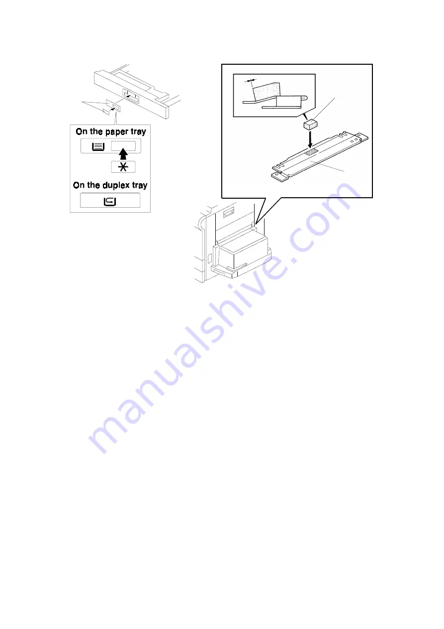
33. Attach the cushion [B] at the center of the LCT upper stay [C] as shown.
NOTE: Make sure that the edge of the cushion is aligned with the line
where the stay is bent at a slight angle.
[A]
A212I510.wmf
A212I511.wmf
[B]
[C]
A212I512.img
INSTALLATION
13 October 1997
34
Summary of Contents for A212
Page 10: ...MEMO A212 A214 Copier 13 October 1997 MACHINE CONFIGURATION 7...
Page 82: ...COPIER ELECTRICAL COMPONENT LAYOUT 2 3 4 5 6 7 8 1 12 11 10 13 9 A212S500 wmf...
Page 84: ...42 43 44 45 46 47 49 50 51 53 56 57 58 64 63 62 61 60 59 48 52 55 54 A212S502 wmf...
Page 85: ...65 66 67 68 69 70 71 72 73 75 74 79 78 77 76 80 83 82 81 A212S503 wmf...


