


RHE26/27 Installation & Startup Guide – Doc. No. 8.2.1.06 – Ver. 1.40
21
The value of this menu item will be a number between 0 and 7. Details of the correct setting for
this parameter are provided below each of the various wiring schemes found in section 3.2.1.
SERVICE access level passcode is required to access the temperature configuration menu.
4.6
Input/Output Configuration
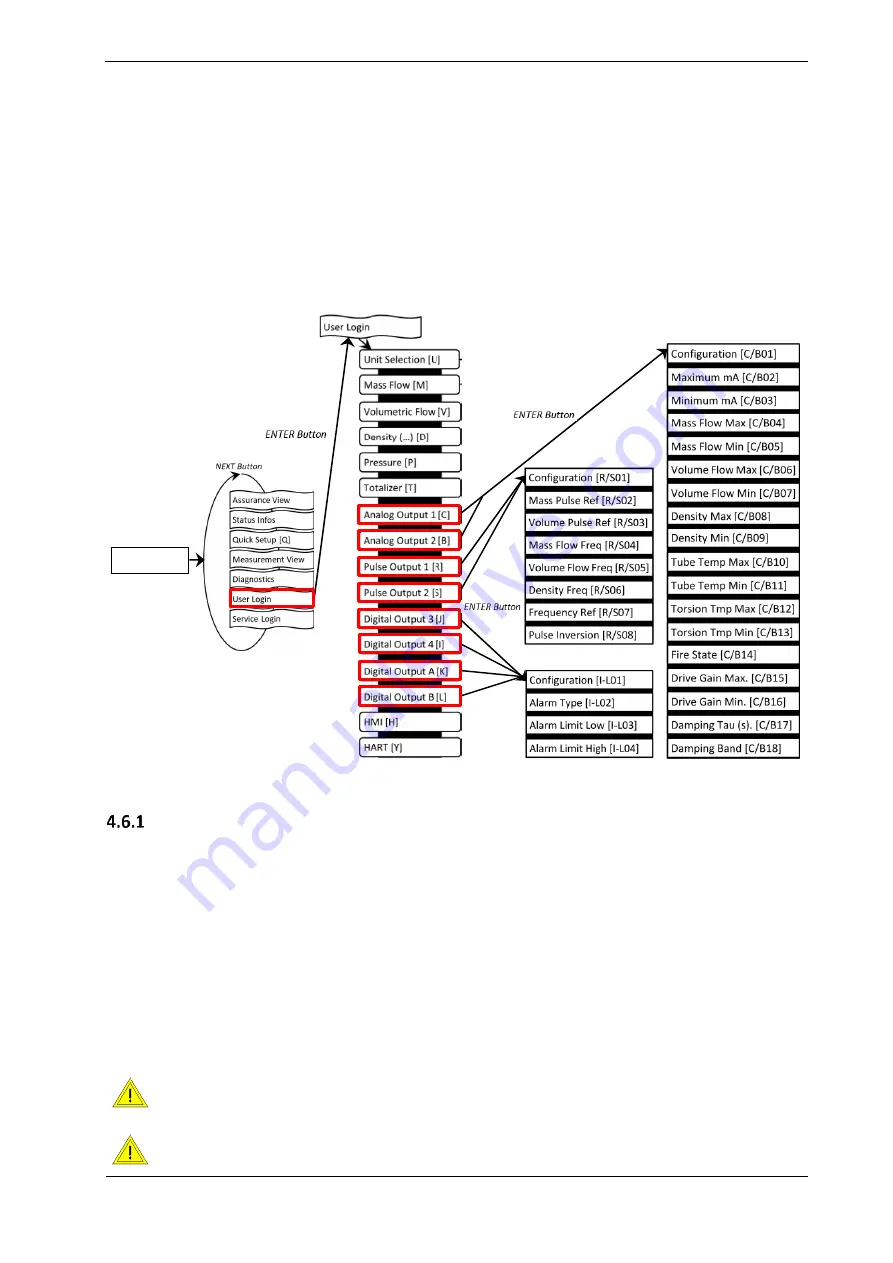
To configure the analog and digital outputs, navigate to the respective menu items under User
Login (Figure 18).
Analog Output Configuration
1.
Select “Analog Output” 1 [C] or 2 [B] and press “ENTER” [
] to get to the “Configuration”
[C/B01] menu
2.
Select one of the options stated in Table 9 under ID [C/B01], e.g. Configuration 3 – Density
3.
The default settings are: “Maximum mA” [C/B02] = 20mA; “Minimum mA” [C/B03] = 4mA.
This can be changed if necessary
4.
Assign the maximum and minimum of the measured variable to respective mA level,
e.g. 1200 kg/m³ for “Density Max” [C/B08] and 0 kg/m³ for “Density Min” [C/B09]
5.
Select a fire state configuration [C/B14] to determine what shall happen if the measured
variable range is exceeded or in case of error condition
6.
If necessary set a damping factor [C/B17] and damping band range [C/B18]
The RHE26 has only one analog output. For configuration use “Analog Output 2 [B]”.
If the RHE27 is equipped with only one analog output use “Analog Output 2 [B]” for
configuration.
0
Main Screen
Figure 18: RHE26/27 Menus - Output Configuration


