


9
2.5 CLEARANCES
• All units are designed for “0” inches clearance to combustible material on all cabinet
surfaces.
• Units with electric heat require a one inch clearance to combustible material for the
first three feet of supply plenum and ductwork.
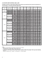
• Some units require a combustible floor base depending on the heating kW. The fol-
lowing table should be used to determine these requirements.
Additionally, if these units are installed down-flow, a combustible floor base is
required. See Accessories for Combustible Floor Base RXHB-XX.
Units with electric heating kW equal to or less than the values listed in the table do
not require a combustible floor base.
• Vertical units require clearance on at least one side of the unit for electrical connec-
tions. Horizontal units require clearance on either top or bottom for electrical connec-
tions. Refrigerant and condensate drain connections are made on the front of the unit.
(See Figure 4.)
• All units require 24 inches maximum access to the front of the unit for service.
• These units may be installed in either ventilated or nonventilated spaces.
3.0 APPLICATIONS
3.1 ZONING SYSTEMS
The manufacturer does not currently provide or support zoning. However, zoning systems
can be installed with a variable speed air-handler as long as the zoning equipment manu-
facturers specifications and installation instructions are met and followed.
The preferred zoning method is to use a “bypass” system which is properly installed for
maximum efficiency. In these systems, excess air is routed back through the system to
be used again – this is opposed to a “dump” system in which excess air is routed to a
zone where it is expected that the extra heat or cooling would be least noticed.
If installed as a “bypass” system, the installation must have an optional freeze stat
installed to prevent the coil from icing with excess bypass cooling. Also, if the zoning
equipment manufacturer provides a limit switch (usually provided by the zoning manufac-
turer), this limit must be installed in the system to prevent the furnace from overheating.
FIGURE 4
DIMENSIONS FOR FRONT CONNECT COIL
4
1
/
8
3
1
/
16
1
3
/
16
1
1
/
8
1
1
/
16
1
3
/
8
2
13
/
16
5
1
/
4
5
3
/
8
5
15
/
16
Model Cabinet Size
17
21
24
Model Designation kW
15
18
20
Summary of Contents for RH1V2417STANJA
Page 54: ...54 FIGURE 44 COMFORT CONTROL2 SYSTEM AIR HANDLER WIRING DIAGRAM H2V...
Page 55: ...55...
Page 56: ...56 CM 0115...