


50
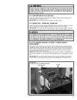
3. While not necessary, it may prove easier to remove the complete blower assembly
from the furnace. Unplug the two cable connectors to the motor. There are latches
on each connector. DO NOT PULL ON THE WIRES. TO REMOVE THE PLUG,
SQUEEZE THE PIN LATCH. The plugs remove easily when properly released.
4. Locate the two standard 1/4" hex head bolts on the flat end of the motor control
module casting. Remove these bolts from the motor while holding the control mod-
ule. DO NOT REMOVE TWO SCREWS WITH TORX HEADS.
5. The control module is still connected to the motor by a plug and cable. Carefully
rotate the control so as to gain access to the plug on the cable end. Squeeze the
release latch and gently pull the plug out of the control module. DO NOT PULL ON
THE WIRES. GRIP THE PLUG ONLY.
6. The control module is now completely detached from the motor. Use an ohmmeter
to measure the resistance from each motor lead (in the motor plug just removed) to
the motor shell. This resistance must be greater than 100K ohms. Always measure
to the unpainted motor end plate. If any motor lead fails this test DO NOT INSTALL
THE NEW CONTROL MODULE.
7. Verify that the replacement control module is correct. Place the new module next to
the motor and carefully insert the plug that was removed in step 5. BE SURE THE
PLUG LATCHES. IT SHOULD CLICK INTO PLACE.
8. Install the new control module back on the motor. Carefully engage the alignment
pin into the appropriate mating motor hole.
9. Replace the two 1/4" hex head bolts. Tighten the bolts snugly. DO NOT OVER
TIGHTEN.
IMPORTANT:
Before replacing the blower motor assembly, check the installation for any
application fault that might have caused the motor or control module to fail. Water dam-
age could show as corrosion on the inside or outside of the casting. If so, run a Moisture
Check.
10. Install the blower motor assembly back into the furnace. Follow the manufacturer’s
suggested procedures.
11. Plug the
control connector
into the motor. The connector is keyed. Be sure the
connector is properly seated and latched.
12. Plug the
control connector
into the motor. The connector is keyed. Be sure the
connector is properly seated and latched. OBSERVE THE PROPER ORIENTA-
TION. DO NOT FORCE THE CONNECTOR. It plugs in very easily when properly
oriented.
!
CAUTION
Reversing the 5-pin connector on the ECM motor causes immediate failure of
the control module.
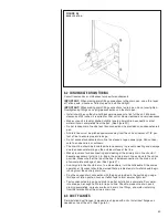
FIGURE 40
ECM MOTOR COMPONENTS
FIGURE 41
MOTOR ALIGNMENT PIN
!
WARNING
Always have 240 volt power turned off to the furnace before attempting any
replacement of the motor or control module. Failure to do so may result in seri-
ous equipment damage, personal injury or death.
Summary of Contents for RH1V2417STANJA
Page 54: ...54 FIGURE 44 COMFORT CONTROL2 SYSTEM AIR HANDLER WIRING DIAGRAM H2V...
Page 55: ...55...
Page 56: ...56 CM 0115...