


B. If air handler is away from wall attach pipe strap to top of air handler using No. 10
1
⁄
2
long self-tapping screws on both sides. Angle strap down and away from back
of air handler, remove all slack, and fasten to wall stud of structure using
5
⁄
16
lag
screws 1
1
⁄
2
long. Secure bottom of unit with two 16ga “L” brackets with No. 10
self-tapping screws to air handler and use
5
⁄
16
lag screws 1
1
⁄
2
long to floor.
4.0 ELECTRICAL WIRING
Field wiring must comply with the National Electric Code (C.E.C. in Canada) and any
applicable local ordinance.
4.1 POWER WIRING
It is important that proper electrical power is available for connection to the unit model
being installed. See the unit nameplate, wiring diagram and electrical data in the installa-
tion instructions.
• If required, install a branch circuit disconnect of adequate size, located within sight of,
and readily accessible to the unit.
• IMPORTANT:
After the Electric Heater is installed, units may be equipped with one,
two, or three 60 amp. circuit breakers. These breaker(s) protect the internal wiring in
the event of a short circuit and serve as a disconnect. Circuit breakers installed within
the unit do not provide over-current protection of the supply wiring and therefore may
be sized larger than the branch circuit protection.
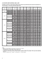
• Supply circuit power wiring must be 75°C minimum copper conductors only. See
Electrical Data in this section for ampacity, wire size and circuit protector requirement.
Supply circuit protective devices may be either fuses or “HACR” type circuit breakers.
• Power wiring may be connected to either the right, left side or top. Three
7
/
8
”, 1
3
/
32
”,
1
31
/
32
” dia. concentric knockouts are provided for connection of power wiring to unit.
• Power wiring is connected to the power terminal block(s) in unit control compartment.
!
WARNING
Disconnect all power to unit before installing or servicing. More than one dis-
connect switch may be required to de-energize the equipment. Hazardous volt-
age can cause severe personal injury or death.
13
FIGURE 8
ST-A-1193-01
Summary of Contents for RH1V2417STANJA
Page 54: ...54 FIGURE 44 COMFORT CONTROL2 SYSTEM AIR HANDLER WIRING DIAGRAM H2V...
Page 55: ...55...
Page 56: ...56 CM 0115...