Rheem RH1V2417STANJA Installation Instructions Manual Download Page 30

30

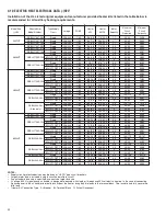
5.10 AIRFLOW PERFORMANCE (-)H1V

Airflow performance data is based on cooling performance with a coil and no filter in
place. Select performance table for appropriate unit size, voltage and number of electric
heaters to be used. Make sure external static applied to unit allows operation within the
minimum and maximum limits shown in table below for both cooling and electric heat
operation. For optimum blower performance, operate the unit in the .1 [3 mm] to 1.00
inches [25 mm] W.C. external static range. Units with coils should be applied with a mini-
mum of .1 inch [3 mm] W.C. external static.

Nominal

Cooling

Capacity

Tons

Model

Size

(-)H1V

Motor

Speed

From

Factory

Nominal

Air-Flow

CFM

Blower

Size

Motor

H.P.

CFM Air Delivery/RPM/Watts-230 Volts (No Filter)

External Static Pressure-Inches W.C.

0.10

0.20

0.30

0.40

0.50

0.60

0.70

0.80

0.90

1.00

CFM

597

608

607

616

616

618

613

608

600

594

RPM

522

609

673

757

815

869

938

995

1051

1097

Watts

57

74

89

115

130

144

169

190

212

232

CFM

588

598

596

605

603

605

600

595

587

577

RPM

536

608

723

805

864

919

989

1047

1104

1149

Watts

65

85

100

129

145

160

186

209

233

254

CFM

787

805

815

819

810

807

811

810

809

805

RPM

614

682

763

818

868

917

972

1017

1070

1112

Watts

97

113

144

167

191

209

239

259

289

311

CFM

775

793

803

807

798

795

799

798

797

793

RPM

630

700

783

839

891

941

997

1044

1098

1141

Watts

111

130

165

192

219

240

275

298

332

357

CFM

1001

1030

1030

1035

1035

1029

1029

1029

1029

1023

RPM

652

752

812

845

923

945

1007

1065

1090

1118

Watts

134

166

193

212

244

266

280

320

341

357

CFM

980

1009

1009

1014

1014

1008

1008

1008

1008

1002

RPM

714

814

874

907

985

1007

1069

1127

1152

1180

Watts

176

208

235

254

286

308

322

362

383

399

CFM

1220

1229

1229

1229

1229

1229

1238

1238

1233

1228

RPM

732

831

875

930

981

1005

1077

1108

1156

1194

Watts

215

253

282

314

348

362

409

426

472

496

CFM

1199

1208

1208

1208

1208

1208

1217

1217

1212

1207

RPM

794

893

937

992

1043

1067

1139

1170

1218

1256

Watts

257

295

3245

356

390

404

451

468

514

538

CFM

1001

1001

1011

1009

1005

1000

996

994

970

967

RPM

620

694

767

830

888

941

1004

1048

1128

1179

Watts

128

122

195

217

229

270

289

302

380

388

CFM

1175

1200

1203

1200

1200

1199

1202

1200

1197

1180

RPM

664

740

805

868

926

982

1031

1087

1138

1196

Watts

163

191

226

239

261

292

322

373

420

472

CFM

1000

1001

1011

1009

1005

1000

996

994

970

967

RPM

593

650

737

801

867

914

980

1026

1058

1099

Watts

103

124

155

177

207

224

258

287

301

323

CFM

984

979

984

976

967

956

947

939

910

901

RPM

627

689

780

849

919

971

1041

1092

1128

1174

Watts

124

151

187

215

250

273

312

347

366

394

CFM

1175

1200

1203

1200

1200

1199

1202

1200

1197

1180

RPM

646

740

783

851

911

958

1013

1056

1102

1144

Watts

147

186

207

240

270

296

334

356

385

416

CFM

1159

1178

1176

1167

1162

1155

1153

1145

1137

1114

RPM

680

779

826

899

963

1015

1074

1122

1172

1219

Watts

168

213

239

278

313

345

388

416

450

487

CFM

1393

1405

1410

1419

1422

1422

1419

1416

1407

1406

RPM

769

830

886

958

1014

1069

1118

1152

1204

1232

Watts

247

266

296

347

369

408

463

492

521

552

CFM

1590

1605

1610

1625

1628

1628

1623

1620

1613

1599

RPM

852

917

962

1034

1081

1132

1178

1220

1258

1292

Watts

350

382

385

419

501

537

584

599

647

689

CFM

1395

1404

1413

1413

1411

1411

1402

1391

1380

1371

RPM

731

807

859

910

968

1016

1057

1100

1128

1158

Watts

240

273

308

349

383

411

436

468

496

513

CFM

1379

1382

1386

1380

1373

1367

1353

1336

1320

1305

RPM

765

846

902

958

1020

1073

1118

1166

1198

1233

Watts

261

300

340

387

426

460

490

528

561

584

CFM

1583

1583

1583

1590

1582

1566

1572

1556

1547

1539

RPM

826

879

933

984

1025

1067

1119

1148

1176

1219

Watts

342

375

410

454

486

523

552

585

614

616

3617ST

No heat

3617ST

with

18kw heat

3617ST

No heat

3617ST

with

18kw heat

High

High

1000*

1000*

10x8

1/2

10x8

1/2

2417ST

No Heat

High

600*

10x8

1/3 [249]

5 Speed

1.5

2417ST

with 13kw

Heater

High

600*

10x8

1/3 [249]

5 Speed

1.5

2417ST

No Heat

High

800

10x8

1/3 [249]

5 Speed

2

2417ST

with 13kw

Heater

High

800

10x8

1/3 [249]

5 Speed

2

2.5

2.5

High

1200

10x8

1/2

3.0

3.0

High

1200

10x8

1/2

3621MT

with

15kw heat

2.5 ton

High

1000

10x10

3/4

3621MT

No heat

3.0 ton

High

1200

10x10

3/4

3621MT

with

18kw heat

3.0 ton

High

1200

10x10

3/4

4821MT

No heat

3.5 ton

High

1400

10x10

3/4 Hp

4821MT

No heat

4 ton

High

1600

10x10

3/4 Hp

5.11 AIRFLOW PERFORMANCE DATA (-)H1V

3621MT

No heat

2.5 ton

High

1000

10x10

3/4

3621HT
No heat

2.5 ton

High

1000

10x10

1/2 Hp

3621HT
No heat

3 ton

High

1200

10x10

1/2 Hp

4821ST

No heat

4821ST

with

20kw heat

4821ST

No heat

3.5

High

1400*

10x10

3/4

4.0

3.5

High

High

1600

1400*

10x10

3/4

10x10

3/4

Summary of Contents for RH1V2417STANJA

Page 1: ...instructions are intended as an aid to qualified licensed service personnel for proper installation adjustment and operation of this unit Read these instructions thoroughly before attempting installa...

Page 2: ...low Performance Data 32 6 2 Copper Wire Size Awg 3 Voltage Drop 33 6 3 Blower Motor Electrical Data H2v 33 6 4 Electric Heat Electrical Data 33 6 5 Cooling Airflow Settings 34 6 6 Cooling Airflow Adju...

Page 3: ...ll joints seams and openings in the equipment and duct must also be sealed to prevent depressurization of the space and possible migration of combustion byproducts including carbon monoxide into the l...

Page 4: ...intained WARNING SEE SECTION 8 0 DUCTWORK Do not under any circumstances connect return ductwork to any other heat pro ducing device such as fireplace insert stove etc Unauthorized use of such devices...

Page 5: ...unconditioned space This can result in property damage NOTICE Improper installation or installation not made in accordance with the Underwriters Laboratory UL certification or these instructions can...

Page 6: ...re field installed items 4 The air handlers do not have an internal filter rack An external filter rack or other means of filtration is required 2 2 MODEL NUMBER EXPLANATION SEE FIGURE 2 AVAILABLE MOD...

Page 7: ...MATCHED TO OUTDOOR UNIT1 ODD ODD Normal Normal 1ST STAGE 2ND STAGE UNIT WITH COIL MAX kW NOMINAL COIL AIRFLOW L s UNIT WEIGHT SHIPPING WEIGHT LBS kg 2421HT 21 533 421 2 1080 191 2 495 ARL ASL 024JEC...

Page 8: ...ants such as dirt dust fumes and odors into the home causing property damage Fumes and odors from toxic volatile or flammable chemicals as well as automobile exhaust and carbon monoxide CO can be draw...

Page 9: ...ice These units may be installed in either ventilated or nonventilated spaces 3 0 APPLICATIONS 3 1 ZONING SYSTEMS The manufacturer does not currently provide or support zoning However zoning systems c...

Page 10: ...and the National Electric Code for horizontal right application the circuit breaker s on field installed electric heater kits must be re installed per procedure below so that the breaker switch on po...

Page 11: ...is loop Rotate unit into the downflow position with the coil compartment on top and the blower com partment on bottom The set of coil rails must be moved for vertical down flow and horizontal right ap...

Page 12: ...can be wrapped with insulation This can be done as long as the unit is completely enclosed in insulation sealed and service access is provided to prevent accumulation of moisture inside the insulation...

Page 13: ...ric Heater is installed units may be equipped with one two or three 60 amp circuit breakers These breaker s protect the internal wiring in the event of a short circuit and serve as a disconnect Circui...

Page 14: ...after installation separation of control wiring and power wiring has been maintained FIELD WIRE SIZE FOR 24 VOLT THERMOSTAT CIRCUITS Thermostat Load Amps 3 0 2 5 2 0 16 16 18 50 14 14 16 100 12 12 14...

Page 15: ...WITH ELECTRIC HEAT AND USING A HUMIDISTAT FOR DEHUMIDIFICATION B W2 G Y W1 B ODD C R Air Handler Y G W2 E Heat PumpThermostat Heat Pump Outdoor Unit Y B Humidistat C R R D C Y2 Field Installed Line V...

Page 16: ...Unit Y2 C R Y2 Field Installed Line Voltage WIRING INFORMATION Factory Standard ODD R Y1 Y2 G W2 R Y1 C L Y Y BL R BR W R DHM L W1 FIGURE 18 2 STAGE CONDENSING UNIT WITH ELECTRIC HEAT USING A TWO STA...

Page 17: ...W1 G BK W BK BL G Y BR R Y2 Y BL FIGURE 21 TYPICAL SINGLE STAGE THERMOSTAT SINGLE STAGE STRAIGHT COOLING WITH ELECTRIC HEAT 2ND STAGE AIR FLOW G W2 C R Single Stage A CThermostat A C Outdoor Unit C Y...

Page 18: ...nit must be permanently grounded Failure to do so can result in electri cal shock causing personal injury or death 4 6 BLOWER MOTOR ELECTRICAL DATA H1V MAXIMUM CIRCUIT PROTECTOR MINIMUM CIRCUIT AMPACI...

Page 19: ...jumpered together to energize all the electric heat when a call for electric heat is received if warmer supply air is desired NOTE When using 24VAC thermostat control wiring the serial communicating c...

Page 20: ...8 1 60 1 4 8 SINGLE 17 3 20 0 4 0 27 30 30 30 RXBH 1724 07J 5 4 7 2 1 60 2 3 6 SINGLE 26 0 30 0 4 0 38 43 40 45 RXBH 1724 10J 7 2 9 6 1 60 2 4 8 SINGLE 34 6 40 0 4 0 49 55 50 60 10 8 14 4 1 60 3 4 8...

Page 21: ...3 2 SINGLE 40 0 46 2 4 4 56 64 60 70 RXBH 24A20C 7 2 9 6 3 60 3 3 2 MULTIPLE CKT 1 20 0 23 1 4 4 31 35 35 35 7 2 9 6 3 60 3 3 2 MULTIPLE CKT 2 20 0 23 1 0 25 29 25 30 RXBH 24A25C 18 0 24 0 3 60 6 4 0...

Page 22: ...0 8 35 4 4 9 45 60 45 51 MULTI CKT 2 208 240 1 60 6 4 8 5 30 8 35 4 0 40 45 39 45 Single 208 240 1 60 14 4 19 2 69 2 80 0 4 9 100 110 93 107 RXBH 24A20J MULTI CKT 1 208 240 1 60 7 2 9 6 34 6 40 0 4 9...

Page 23: ...ng where the breakers apply has been UL approved for short circuit protection Ampacity not breaker size determines supply circuit wire size The ampacity listed on the unit rating plate and the Maximum...

Page 24: ...to 1 0 W C The interface board pro vides the required communications between the thermostat and the ECM blower motor The H1V series of air handlers feature An automotive style ATC blade fuse for trans...

Page 25: ...SEE FIGURE 25 The H1V series of air handlers allow a wide range of airflow settings for cooling and heat pump operation These airflow settings are selected via DIP switches 1 and 2 on the interface b...

Page 26: ...switches 5 and 6 control electric heat air flow levels on H1V air handlers FIGURE 26 COOLING AIRFLOW ADJUSTMENTS H1V COOLING SELECTION SWITCH 3 SWITCH 4 AIRFLOW POSITION POSITION ADJUSTMENT A OFF OFF...

Page 27: ...e and airflow through the duct system TABLE 3 H1V S8 S7 S7 S8 On On Off On Off Ramp Times CFMReduction 5 minutes 18 Less 5 to 12 5 minutes 12 Less after 12 5 minutes 100 Full Operating Sequence Pre pr...

Page 28: ...dehu midification in the cooling mode that is controlled by the user s dehumidifying thermostat or humidistat setting When the humidity exceeds the humidistat setting the airflow is decreased by a pre...

Page 29: ...24VAC 600 1000 1400 1600 TABLE 5 SELECTION C EXPLANATION ON DEMAND DEHUMIDIFICATION ACTIVE H1V CABINET SIZE COOLING CAPACITY SWITCH POSITIONS FIGURE 29 ON DEMAND DEHUMIDIFICATION AIRFLOW ADJUSTMENT A...

Page 30: ...1202 1200 1197 1180 RPM 664 740 805 868 926 982 1031 1087 1138 1196 Watts 163 191 226 239 261 292 322 373 420 472 CFM 1000 1001 1011 1009 1005 1000 996 994 970 967 RPM 593 650 737 801 867 914 980 102...

Page 31: ...s 246 325 369 401 459 495 532 572 509 652 CFM 1794 1808 1808 1808 1807 1807 1807 1800 1786 1772 RPM 676 739 787 840 871 923 950 994 1028 1050 Watts 330 376 416 465 504 554 576 624 662 694 CFM 1756 177...

Page 32: ...mmunicating control will assume the control is being used with a traditional thermostat and will IGNORE ANY COMMUNICATIONS USING DATA WIRE 1 AND DATA WIRE 2 IMPORTANT Class 2 low voltage control wire...

Page 33: ...TANT If the RX DATA LED is solid green data wire 1 and data wire 2 are not properly connected Typically the connections are switched i e data wire 1 is wired to the data wire 2 connection and data wir...

Page 34: ...eration only They are ignored when in heating mode or when electric heat is activated 6 7 ELECTRIC HEAT AIRFLOW H2V The H2V series of air handlers are factory programmed to provide adequate airflow fo...

Page 35: ...to bring the blower up to 50 airflow for 30 seconds before advancing to 100 airflow This minimizes air flow sounds at system startup Profile C Humid Climate Profile The humid profile is configured to...

Page 36: ...e stage condensing units Refer to the Engineering Specifications Sheets to determine the required airflow for your particular combination Refer to Table 5 to determine the air flows available for each...

Page 37: ...AIRFLOW The RHPN series air handlers are shipped with the Low KW airflow feature turned OFF Activate lower airflow feature for lower KW electric heat applications by turning DIP switch 8 ON IMPORTANT...

Page 38: ...for cooling operation only They are ignored when the heat pump is in heating mode or when electric heat is activated 6 16 COOLING DELAY PROFILES H2V Cooling delay profiles are not available when the H...

Page 39: ...1044 289 334 377 417 456 493 529 562 593 623 1050 1050 1075 1075 1050 1025 1025 1025 1025 1000 525 575 625 675 750 800 825 875 925 975 100 125 150 175 225 250 275 300 325 350 1625 1625 1650 1675 1675...

Page 40: ...ce T d8 Old Shared Data System data is obsolete If system will not operate order new memory card to update system information T T T T 68 ECM No Signal The ECM motor is not communicating to the air han...

Page 41: ...MPORTANT Flanges around blower opening for attaching supply duct must be up out of blower discharge even if not used so they do not restrict airflow from blower IMPORTANT If an elbow is included in th...

Page 42: ...om being damaged by torch flames After the refrigerant connections are made seal the gap around the connections with pressure sensitive gasket If necessary cut the gasket into two pieces for a better...

Page 43: ...nsulated where necessary to prevent sweating and damage due to condensate forming on the outside surface of the line Make provisions for disconnecting and cleaning of the primary drain line should it...

Page 44: ...B energizes the reversing valve RV switching it to the heating position remains energized as long as system switch is in heat position Circuit R and Y energizes the contactor CC starting the outdoor f...

Page 45: ...when the fan switch is in the auto position 10 6 ROOM THERMOSTAT ANTICIPATOR SETTING See instructions with outdoor section condensing unit or heat pump for recommended room thermostats On units with...

Page 46: ...ead all WARNINGS listed in these installation instructions PRE START CHECKLIST Is unit properly located level secure and service able Has auxiliary pan been provided under the unit with separate drain...

Page 47: ...able in Section 5 20 NOTE The memory card is attached to the control box with a tether The tether has an identification label that can be used to identify the memory card if replacement is need ed IMP...

Page 48: ...blower deck Make sure blower assembly engages lances in deck properly If assembly hangs up check to make sure top and bottom are lined up in proper locations Slide blower assembly to back of cabinet...

Page 49: ...r wheel is centered in the blower housing with the same dis tance on each side between the inlet venturi and the outside of the blower wheel Re assemble the motor wiring high and low voltage plugs int...

Page 50: ...or and carefully insert the plug that was removed in step 5 BE SURE THE PLUG LATCHES IT SHOULD CLICK INTO PLACE 8 Install the new control module back on the motor Carefully engage the alignment pin in...

Page 51: ...ugh discharge opening in the blower housing Hold blower wrap down into position and replace two screws holding blower wrap to blower sides See motor replacement and blower assembly instructions for re...

Page 52: ...re 42 Model Cabinet Size Filter Size Part Number A B 17 16 x 20 406 x 508 RXHF 17 15 70 17 50 21 20 x 20 508 x 508 RXHF 21 19 20 21 00 24 25 x 20 635 x 508 RXHF 24 22 70 25 50 Accommodate 1 or 2 filte...

Page 53: ...RXBM Coil Model Horizontal Adapter Kit Horizontal Adapter Kit Model Number Single Qty Model Number 10 pak Qty 2414 RXHH A01 RXHH A01x10 2417 RXHH A02 RXHH A02x10 3617 3621 RXHH A03 RXHH A03x10 3821 4...

Page 54: ...54 FIGURE 44 COMFORT CONTROL2 SYSTEM AIR HANDLER WIRING DIAGRAM H2V...

Page 55: ...55...

Page 56: ...56 CM 0115...

Reviews: