37
FIELD-INSTALLED
OPTION ACCESSORIES
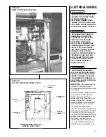
ELECTRONIC AIR CLEANER
Line voltage power can be supplied
from the screw terminal “EAC” and a
line voltage neutral screw terminal on
the control board. This will power the
electronic air cleaner whenever the
circulating air blower is in operation.
HUMIDIFIER
Line voltage power can be supplied
from screw terminal “HUM” to a line
voltage neutral screw terminal on the
control board. This will power the
humidifier whenever the burner is
on and the circulating air blower is
operating in the heating mode.
NOTE: Maximum current – 1.0 amps
for each option.
HIGH ALTITUDE KIT
Models installed at altitudes of 5,000
feet and above require a pressure
switch change. These may be
ordered under Option Code No. 278.
Models with this option code will have
the additional pressure switch and
burner orifice packed with the
furnace. The installer should replace
the induced draft blower pressure
switch installed on the furnace with
the new pressure switch. The burner
orifices should also be changed when
required (See Table Below). The
following high altitude kits are also
available:
Kit No: RXGY-F04 – set point – 0.70" w.c.
RXGY-F05 – set point – 0.60" w.c.
RXGY-F06 – set point – 1.11" w.c.
RXGY-F07 – set point – 0.95" w.c.
The following is a list of furnace in-
puts and required pressure switches:
INPUT
KIT NO.
SET POINT
MAKE POINT
45,000
RXGY-F06
1.11" w.c.
1.29" w.c.
60,000
RXGY-F06
1.11" w.c.
1.29" w.c.
75,000
RXGY-F07
0.95" w.c.
1.10" w.c..
90,000
RXGY-F06
1.11" w.c.
1.29" w.c..
105,000
RXGY-F04
0.70" w.c.
0.85" w.c.
120,000
RXGY-F05
0.60" w.c.
0.75" w.c.
ORIFICE SIZES
U.S.
0 - 7999 FT.
8000 FT. & ABOVE
Natural Gas
#50
#51
LP Gas
1.15 mm
1.10 mm
CANADA
0 - 2000 FT.
2001 TO 4500
Natural Gas
#50
#50
LP Gas
1.15 mm
1.15 mm
NOTICE: DO NOT
make any attempt
to rerate the furnace by changing gas
orifices or the gas pressure. Allow the
natural derate of the gas to occur.
The natural derate is approximately
1.8% per 1000 feet.
No orifice sizing or other derate
procedures are necessary unless the
natural gas exceeds 1075 BTU/cu. ft.
at sea level or the LP gas exceeds
2500 BTU/cu. ft. at sea level. If the
heating values exceed these levels,
consult the manufacturer for the
derate procedures.
FURNACE TWINNING
INSTALLATIONS
Twinning operation of two furnaces,
installed side-by-side, connected by a
common duct system with main
power supplied by the same source,
and controlled by a common
thermostat can be done with the
Honeywell S9201E2001, UTEC 1012-
920 or 1028-927 and Johnson
Controls G961DAJ-2401 integrated
control boards.
IMPORTANT: TWINNING OF (-)GRJ-
AND (-)GTJ- UNITS REQUIRES AN
ACCESSORY TWINNING KIT.
REFER TO THE SPECIFICATION
SHEET FOR PROPER KIT. DO NOT
ATTEMPT TO TWIN THESE
MODELS BY USING THE
INSTRUCTIONS BELOW.
It should be noted that both blowers
will run simultaneously when there is
a call for heating, cooling or fan.
The “OK” LED will flash if twinning is
not set up properly.
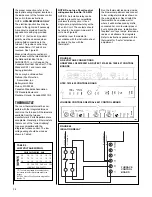
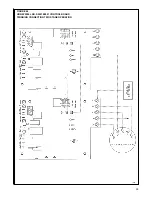
HONEYWELL S9201E2001
CONTROL BOARD
1. Single Stage Operation
(See Figure 45)
a. Control board “ONE” is
connected to the thermostat.
b. Remove the jumper between
the “XMIT” and “RCV”
terminals.
c. Connect wire from “XMIT”
terminal of board “ONE” to
“RCV” terminal of board
“TWO.”
d. Connect wire from “RCV”
terminal of board “ONE” to
“XMIT” terminal of board
“TWO.”
e. Connect wire between the
grounds.
f. Connect wire between the two
“W” thermostat terminals.
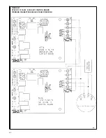
2. Two Stage Operation
(See Figure 46)
a. Repeat steps a, b, c, d and e
above.
b. Connect “W1” of thermostat to
“W” on control board “ONE”.
c. Connect “W2” of thermostat to
“W” on control board “TWO”.
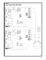
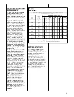
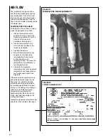
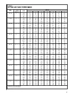
UTEC 1012-920 & 1028-927
CONTROL BOARDS
1. Single Stage Operation
(See Figure 47)
a. Control board “ONE” is on
furnace connected to the
thermostat.
b. The 24 VAC supply to both
control boards must be in
phase with each other.
c. Connect the “C,” “W” and
“TWIN” terminals to
counterparts on each control.
d. Both control boards must have
switch #3 in the “ON” position.
e. Control board “ONE” must
have the switch #4 in the “1st”
position. The other control
board must have switch #4 in
the “ON” position for single
stage heat operation.
NOTE:
The 1028-927 control board
has no 4th, 1st-2nd switch,
Staging is determined through
“W” terminal connections only.
2. Two Stage Operation
(See Figure 48)
a. Follow above instructions:
Switch #4 on control board
“TWO” must be in “2nd”
position. Control board “TWO”
must be
the slave (not
connected to the thermostat)
in two-stage operation.
b. Connect “W2” on thermostat
to “W” on control board
“TWO”.
Johnson Controls G961DAJ-2401
1.
Single Stage Operation
(See Figure 49)
a. Control board “ONE” is on the
furnace connected to the
thermostat.
b. The 24 VAC supply to both
control boards must be in
phase with each other.
c. Connect the “C” “W” and
“TWIN” terminals to counter-
parts on each control.
d. Both control boards must have
switch #1 in the “ON” position.
e. Control board “ONE” must
have switch #2 in the “ON”
position. The other control
board must have switch #2 in
the “OFF” position for single
stage heat.
2.
Two Stage Operation
(See Figure 50)
a. Follow above instructions
except connect “W2” on the
thermostat to “W” on control
board “TWO.”
b. Control board “TWO”
must be
the slave (not connected to
the thermostat) in two-stage
operation.
ACCESSORIES
Summary of Contents for RGRA SERIES
Page 62: ...62...
Page 63: ...63...
Page 64: ...64 Rheem Manufacturing Company Air Conditioning Division Fort Smith Arkansas CM 1197...


