


26
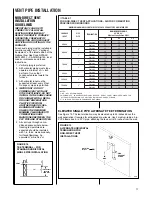
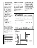
CONNECTING TO FURNACE
IMPORTANT: Clean and debur all
pipe cuts. The shavings must not be
allowed to block the exhaust, inlet or
condensate drain pipes.
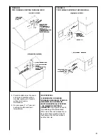
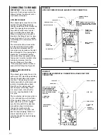
UPFLOW FURNACE
The exhaust pipe connection is a 2-in.
female PVC pipe fitting extending
through the left side of the furnace top
plate. This opening has a protective
cap which should be removed just
prior to installing the exhaust pipe.
When 2-in. pipe is used, connect it
directly to this fitting. When 3-in. pipe
is used, connect a 2 to 3-in. coupling
to this fitting with a short piece of 2-in.
PVC pipe.
The inlet combustion air connection
is at the right side of the top plate.
An alternate combustion inlet air
connection may be made on the right
side of the jacket. This opening has a
plastic cap. A combustion inlet air
connection fitting is supplied with the
furnace and it must be installed in the
furnace by screwing it into the
opening. Make sure the rubber
“O-ring” supplied with the furnace is
used with this fitting. See Figure 26.
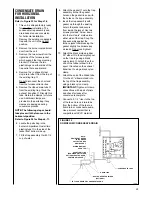
DOWNFLOW/HORIZONTAL
FURNACE
The exhaust pipe connection is a 2-in.
upflow only PVC pipe fitting extending
through the right side of the furnace
top cover. This opening has a pro-
tective cap which should be removed
just prior to installing the exhaust
pipe. When 2-in. pipe is used, con-
nect it directly to this fitting. When
3-in. pipe is used, connect with a
2- to 3-in. coupling directly to the
2-in. pipe.
The combustion inlet air connection is
a 2-in. extruded hole on the left side
of the top plate. When a 2-in. pipe is
used, attach a 2-in. PVC coupling
over this hole with RTV sealant and
also add two sheet metal screws
through the coupling into the
extrusion to secure it in place, and
add the required piping. When 3-in.
pipe is required, use a 2- to 3-in.
coupling and add the required piping.
See Figure 27.
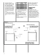
FIGURE 26
UPFLOW COMBUSTION AIR AND VENT PIPE CONNECTION
FIGURE 27
DOWNFLOW/HORIZONTAL COMBUSTION AIR AND VENT PIPE
CONNECTION
VENT CAP/PLUG
VENT CAP/PLUG
OUTLET AIR PIPE
PIPE - PVC
CONNECTOR
CONNECTOR
EXHAUST
TRANSITION
EXHAUST
TRANSITION
PLUG OPT.
COMBUSTION
AIR INLET
POSITION
COMBUSTION AIR
ADAPTER
TOP PLATE
TOP PLATE
“O” RING
COUPLING
NOTE: ATTACH COUPLING
TO EXTRUDED COLLAR
WITH TWO SCREWS. PUT
BEAD OF SILICONE AROUND
BASE BEFORE MOUNTING
COUPLING.
COMBUSTION
AIR CHASE
INDUCED DRAFT
BLOWER
INDUCED DRAFT
BLOWER
CONDENSATE TRAP
NOTE:
WHEN COMBUSTION AIR INLET IS IN
OPTIONAL POSITION, SWAP LOCATION
OF INLET AIR ADAPTER AND “O” RING
WITH PLUG.
PVC
PVC
OUTLET AIR
PIPE
I329
I329
Summary of Contents for RGRA SERIES
Page 62: ...62...
Page 63: ...63...
Page 64: ...64 Rheem Manufacturing Company Air Conditioning Division Fort Smith Arkansas CM 1197...


