METER TIME IN MINUTES AND SECONDS FOR NORMAL
INPUT RATING OF FURNACES EQUIPPED FOR NATURAL
OR LP GAS
INPUT
BTU/HR
METER
SIZE
CU. FT.
HEATING VALUE OF GAS BTU PER CU. FT.
900
1000
1040
1100
2500
MIN. SEC. MIN. SEC. MIN. SEC. MIN. SEC. MIN. SEC.
ONE
1
5
1
12
1
15
1
18
3
20
50,000
TEN
10
50
12
00
12
30
13
12
30
00
ONE
0
44
0
48
0
50
0
53
2
0
75,000
TEN
7
12
8
0
8
19
8
48
20
0
ONE
0
33
0
36
0
38
0
40
1
30
100,000
TEN
5
24
6
0
6
15
6
36
15
0
ONE
0
26
0
29
0
30
0
32
1
12
125,000
TEN
4
19
4
48
5
0
5
17
12
0
ONE
0
31
0
24
0
25
0
26
1
0
150,000
TEN
3
36
4
0
4
10
4
20
10
0
Heating Value of Gas (BTU/Ft
3
) x 3600
Input BTU/HR =
Time in Seconds (for 1 cu.ft.) of Gas
TABLE 4
24
FAN CONTROL
The furnace is equipped with an
integrated furnace control which
automatically starts the main blower 30
seconds after the gas valve opens. It
stops the main blower a set time after
the heat call ends. The off timing is
controlled by the first two dip switches
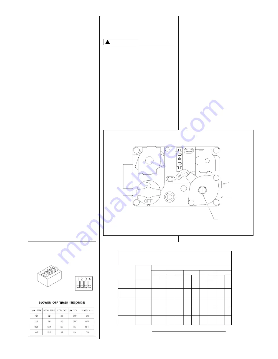
on the control board. See Figure 18.
The blower runs on low speed when the
furnace is in the low fire mode and on
the HEAT speed in the high fire mode.
The integrated control board also
contains the low voltage terminals for
the thermostat connection, and is
located in the blower compartment.
SETTING BLOWER TIMINGS
The control board has six quick connect
terminals for connecting motor speed
leads. These are:
1. LOW – This is low speed. The
motor runs on low when the furnace
is in the low fire mode or when the
thermostat is in the “FAN” position.
2. COOL – Factory wired at high
speed. This may be changed if a
lower cooling speed is desired.
3. HEAT – Factory wired at the normal
high input blower speed.
4. HEAT/COOL – Connect here if the
required HEAT and COOL speeds
are the same.
IMPORTANT:
Do not connect any
leads to the HEAT or COOL terminals if
the HEAT/COOL terminal is used.
5. M1 – Connect unused motor lead.
6. M2 – Connect unused motor lead.
See Figure 18 for instructions for setting
the blower “OFF” timings.
GAS FURNACE (DIRECT
DRIVE) INSTRUCTIONS FOR
CHANGING BLOWER SPEED
DISCONNECT THE ELECTRICAL
SUPPLY TO THE FURNACE BEFORE
ATTEMPTING TO CHANGE THE
BLOWER SPEED. FAILURE TO DO
SO CAN CAUSE ELECTRICAL
SHOCK RESULTING IN SEVERE
PERSONAL INJURY OR DEATH.
The blower motor is wired for blower
speeds required for normal operation.
The LOW speed, which is for the low
fire operation should never be
increased. The HEAT speed is factory
wired for the regular high fire speed.
This may be changed if required to
maintain the proper rise range.
FIGURE 18
BLOWER OFF TIMINGS
UTEC 1095 - 100 CONTROL
BOARD
TWIN
NOTE: SWITCH NO. 3 IS FOR
TWINNING APPLICATIONS
ON
A076201
WARNING
!
Reconnect the unused lead to the M1
or M2 terminal. Check motor lead for
speed designation. Do not reduce the
heating speeds where it could cause
the furnace air temperature rise to
exceed the maximum outlet air
temperatures specified for the unit.
IMPORTANT:
Always check air
temperature rise after changing the
heating speed for any reason.
ADJUSTING OR CHECKING
FURNACE INPUT
The maximum gas supply pressure to
the furnace should be 10.5
(
W.C. for
natural gas. The minimum gas supply
pressure for purposes of input
adjustment to the furnace should be 5
(
W.C.
FIGURE 19
GAS VALVE
INLET
PRESSURE
TAP
OUTLET
PRESSURE
TAP
HIGH FIRE
MANIFOLD
PRESSURE
ADJUSTMENT
LOW FIRE
PRESSURE
MANIFOLD
ADJUSTMENT
Summary of Contents for RGLK
Page 21: ...21 FIGURE 16 UTEC NO 1095 100 CONTROL BOARD TWINNING CONNECTION SINGLE STAGE OPERATION I685 ...
Page 22: ...22 FIGURE 17 UTEC NO 1095 100 CONTROL BOARD TWINNING CONNECTION TWO STAGE OPERATION I684 ...
Page 30: ...30 FIGURE 25 FILTER RETAINING RODS SIDE RETURN FIGURE 26 DOWNFLOW FILTER INSTALLATION ...
Page 32: ...FIGURE 27 INTEGRATED FURNACE CONTROL IFC TROUBLESHOOTING GUIDE FOR UTEC 1095 100 32 ...
Page 33: ...33 ...
Page 34: ...FIGURE 28 UTEC 1095 100 INTEGRATED FURNACE CONTROL 34 ...
Page 35: ...35 ...
Page 36: ...36 CM 997 Rheem Manufacturing Company Air Conditioning Division Fort Smith Arkansas ...


