25
A properly calibrated manometer or
gauge is required for accurate gas
pressure readings.
1. When adjusting the furnace input,
the high fire input should be
checked. The high fire manifold
pressure should be 3.5’ W.C. Follow
these steps to be sure the furnace is
high fire mode:
a. With a single stage thermostat,
the furnace runs for 12 minutes
on low fire before shifting to high
fire. To be certain that it is on high
fire, jump terminals “W” and “W2”
on the control board in the blower
compartment.
b. With a two stage thermostat, set
the thermostat to its highest
setting to keep the furnace
operating in the high fire mode.
2. To adjust high fire manifold
pressure, remove the adjustment
cover screw on the outlet end of the
gas valve and turn the adjustment
screw clockwise to increase the
pressure and counterclockwise to
reduce the pressure. Replace the
cover screw securely. See Figure
19.
3. The low fire manifold pressure
should be 1.7
(
W.C. As mentioned
above, the furnace remains in the
low fire mode for 12 minutes upon a
heat call with a single stage
thermostat. With a two stage
thermostat, disconnect the
thermostat lead to the “W2” terminal
on the control board and the furnace
will remain in the low fire mode. To
adjust the pressure, remove the
regulator cover, on top of the valve,
and adjust as noted under Step 2,
above. After the adjustment replace
the screw cover securely.
NOTE:
Use a 3/32
(
allen wrench for making
the pressure adjustment.
Furnaces for use on LP gas, the LP
gas supply pressure must be set
between 11.0
(
and 13.0
(
W.C. by
means of the tank or branch supply
regulators. The furnace manifold
pressure should be set at 10
(
W.C. at
the gas control valve. For elevations
up to 8,000 feet, rating plate input
ratings apply. For high altitudes
(elevations 8,000 and over) and for
any necessary major changes in the
gas flow rate the orifice spud must be
changed.
To change orifice spuds:
1. Shut off the manual main gas valve
and remove the gas manifold.
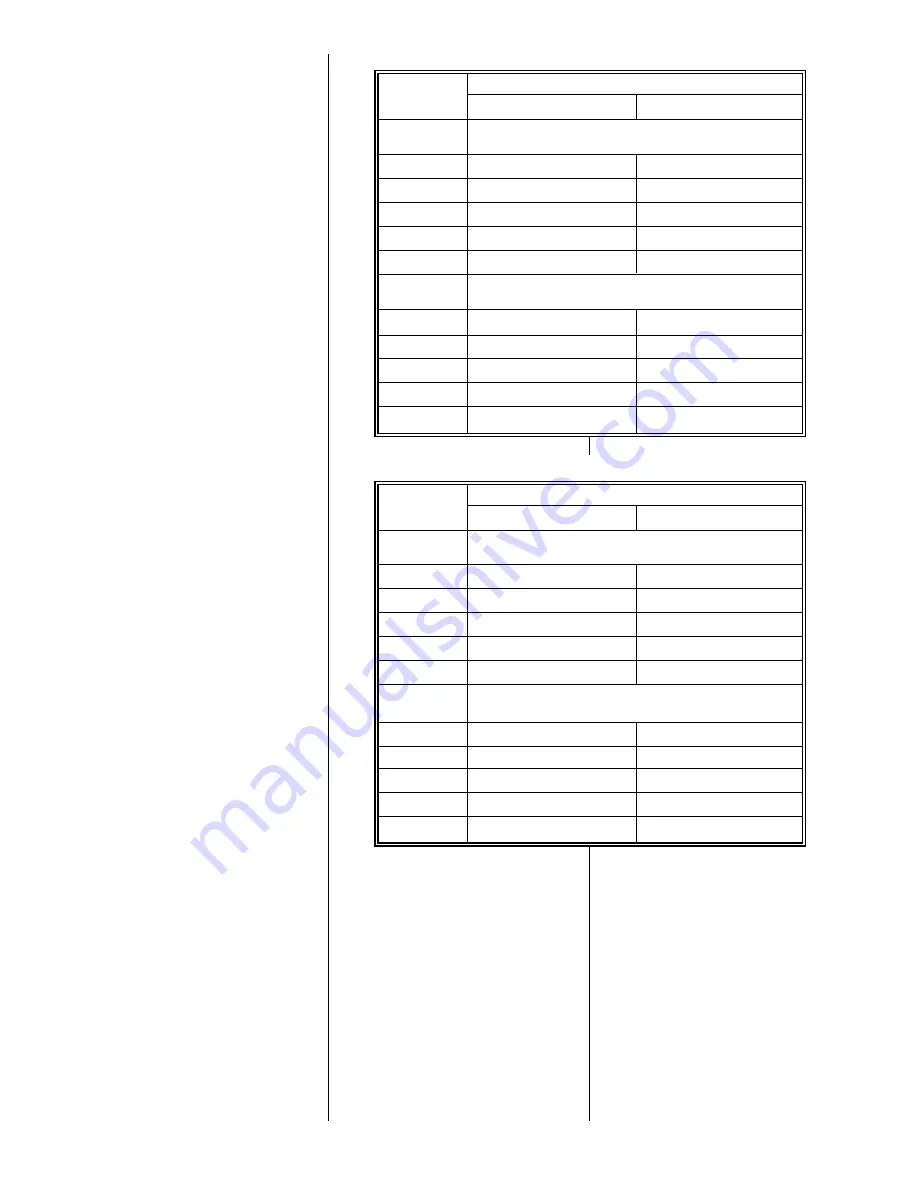
RATING PLATE
ELEVATION
INPUT
BTU/HR
0 TO 7,999 FT.
8,000 FT. AND ABOVE
NATURAL GAS
HEATING VALUE @ 1,000 BTU/FT
3
, SPECIFIC GRAVITY 0.62
MANIFOLD PRESSURE @ 3.5
(
W.C.
50,000
42
43
75,000
42
43
100,000
42
43
125,000
42
43
150,000
42
43
L.P. GAS
HEATING VALUE @ 2,475 BTU/FT
3
, SPECIFIC GRAVITY 1.52/
MANIFOLD PRESSURE @ 10
(
W.C.
50,000
54
55
75,000
54
55
100,000
54
55
125,000
54
55
150,000
54
55
ORIFICE SIZING CHART
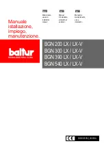
RATING PLATE
ELEVATION
INPUT
BTU/HR
0 TO 1,999 FT.
2,000 FT. TO 4,500 FT.
NATURAL GAS
HEATING VALUE @ 1,000 BTU/FT
3
, SPECIFIC GRAVITY 0.62
MANIFOLD PRESSURE @ 3.5
(
W.C.
50,000
42
42
75,000
42
42
100,000
42
42
125,000
42
42
150,000
42
42
L.P. GAS
HEATING VALUE @ 2,475 BTU/FT
3
, SPECIFIC GRAVITY 1.52/
MANIFOLD PRESSURE @ 10
(
W.C.
50,000
54
54
75,000
54
54
100,000
54
54
125,000
54
54
150,000
54
54
ORIFICE SIZING CHART (CANADA)
2. Replace the orifice spuds.
3. Reassemble in reverse order.
4. Turn the gas supply back on and
check for proper operation and
manifold pressure.
Check of input is important to prevent
over firing of the furnace beyond its
design-rated input. NEVER SET
INPUT ABOVE THAT SHOWN ON
THE RATING PLATE.
To check furnace input:
1. Make certain that all other gas
appliances are shut off, with the
exception of pilot burners.
2. Start the furnace
3. Time the meter to measure the time
required to burn one cubic foot of
gas.
4. Use Table 4 to determine input rate.
Summary of Contents for RGLK
Page 21: ...21 FIGURE 16 UTEC NO 1095 100 CONTROL BOARD TWINNING CONNECTION SINGLE STAGE OPERATION I685 ...
Page 22: ...22 FIGURE 17 UTEC NO 1095 100 CONTROL BOARD TWINNING CONNECTION TWO STAGE OPERATION I684 ...
Page 30: ...30 FIGURE 25 FILTER RETAINING RODS SIDE RETURN FIGURE 26 DOWNFLOW FILTER INSTALLATION ...
Page 32: ...FIGURE 27 INTEGRATED FURNACE CONTROL IFC TROUBLESHOOTING GUIDE FOR UTEC 1095 100 32 ...
Page 33: ...33 ...
Page 34: ...FIGURE 28 UTEC 1095 100 INTEGRATED FURNACE CONTROL 34 ...
Page 35: ...35 ...
Page 36: ...36 CM 997 Rheem Manufacturing Company Air Conditioning Division Fort Smith Arkansas ...


