33
7.0 COMPONENTS & CONTROLS
Components
7.7 Outdoor Ambient
Temperature Sensor
The outdoor ambient temperature is sensed by a
thermistor located directly underneath the control
box where it is shielded from direct sunlight. The
thermistor leads plug into the connector marked OAT
on the 2-Stage Outdoor Control (TSODC).The out
-
door ambient temperature is utilized by the TSODC
and EcoNet
TM
Control Center for several control
functions and is displayed on the EcoNet
TM
Control
Center.
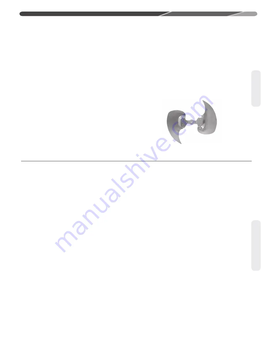
7.8 Outdoor Fan Blade
All models are equipped with a swept fan blade
design that provides improved efficiency and quieter
operation than conventional fan blade designs.
7.9 Outdoor Fan Motor
2, 4, and 5 ton models feature single speed ECM
outdoor fan motors that operates at a speed deter
-
mined by a PWM signal from the 2-stage outdoor
control. The specific speed for each model is pro
-
grammed into the outdoor control memory card at
the factory. A standard single-speed PSC motor is
used on 3 ton model.
8.0 ACTIVE COMPRESSOR PROTECTION
•
If the EcoNet
TM
2-Stage Outdoor Control detects
an operating condition that could be harmful to
the compressor, it will shut the compressor off to
protect it and will lock the compressor out if the
harmful condition persists. This feature is referred
to as Active Compressor Protection.
•
Harmful operating conditions for the compressor
include low suction pressure, high discharge pres
-
sure, high compressor current level, and low line
voltage conditions.
•
Fault codes are displayed on the dual 7-segment
display located on the outdoor unit control. Faults
are also displayed on the EcoNet
TM
Control Center
if one is being used to control the system.
IMPORTANT:
The prefered method of unit
installation is with the EcoNet
TM
communication
system. The EcoNet
TM
communication system allows
access to the fault history of the system. This diag
-
nostic information is not available at the thermostat
when a conventional 24VAC thermostat is used.
•
When the condition causing the lock-out condition
is resolved, the control can be manually reset to
restart the system.
•
To reduce nuisance lock-outs, the control will not
lock the compressor out until the same fault occurs
3 times during a call for operation.
•
A list of fault codes is provided in Section 10.2
of the Diagnostics Section of this manual which
includes those for Active Compressor Protection.
•
If the dual 7-segment LED’s on the control are
displaying an alternating fault code and the letter
“L”, the compressor has been locked out due to the
fault and requires a manual reset for the system to
restart.
•
Exiting Active Protection Compressor
Lock-Out
There are 2 options for resetting the control after
an active compressor protection lock-out.
1.
Cycle 24VAC to the control by removing the
wires connected to the R or C terminals on
the control or cycling the power to the indoor
air-handler or furnace.
2. Push the TEST button down with an insulated
probe for 1 second and release.
WARNING:
The control will attempt to
start the unit immediately when the TEST button is
pushed and released.
Compressor Protection
Summary of Contents for A17 Series
Page 52: ...52...


