background image

User Guide:  RFM5104/14 Predictive Maintenance System User Guide 

Page 1

www.RFMicron.com IN012F13

APPLICATIONS

Protect mechanical plants

Ensure efficient operation

Predictive maintenance

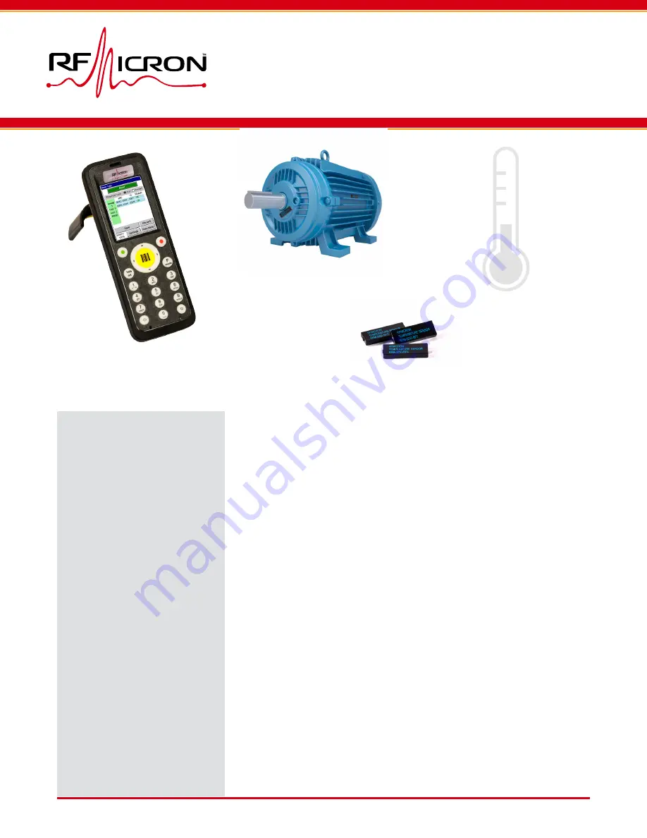
Monitor electric motors

Monitor HVAC efficiency

Monitor AC switchgear

KEY FEATURES

Normal sensor range 

-40 

°

C to +85 

°


High-temperature alarm 

up to +125 

°


Small sensor size 

25.4 x 9.1 x 3.2 mm 


Integrated software

What’s in the system?

This portable predictive maintenance system allows maintenance 
teams to monitor equipment operating temperatures, and it alerts 
on out-of-range performance when equipment exceeds baseline 
alarms. For frequently restarted equipment subject to overheat-
ing risks, the system includes restart alarm settings to alert when 
additional cooling time is needed. The system includes a handheld 
reader with software for Smart Passive Sensing™ devices, as well 
as rugged RFM3250 temperature sensors for use in industrial and 
harsh environments.

How is it used?

The system is used in three phases. Each sensor is physically 
installed on the equipment to be monitored.  The location and ID 
number for each sensor must be assigned or registered with the 
software.  Once the sensor installation is complete, operators 

can read and record sensor values as needed.  Data files from the 

system enable analysis and historical tracking. 

Part numbers

The RFM5104-AF/BF include sensors and a reader conforming to 
FCC frequency ranges, while the RFM5104-AE/BE conform to EU/
ETSI frequency ranges.  The RFM5114 system does not include sen-
sors, but additional sensors can be purchased separately.

RFM5104/5114 USER GUIDE

Predictive Maintenance System


Temperature Monitoring

USER GUIDE - RFM5104/5114

Motors not included

Summary of Contents for RFM5104

Page 1: ...cooling time is needed The system includes a handheld reader with software for Smart Passive Sensing devices as well as rugged RFM3250 temperature sensors for use in industrial and harsh environments How is it used The system is used in three phases Each sensor is physically installed on the equipment to be monitored The location and ID number for each sensor must be assigned or registered with th...

Page 2: ... SCANNER SOFTWARE 8 4 1 Read Sensors Screen 9 4 2 Assign Sensors Screen 10 4 3 Manage Data Files and Result Summary Screens 11 4 4 Settings Screen 12 4 5 Temperature Scanner File Manager 13 4 6 Configuring Mass Storage Mode 15 4 7 Getting the Handheld MAC Address 15 5 DATA FILE FORMATS 16 5 1 Sensor File 16 5 2 Results File 17 5 3 Export File 17 6 VERIFYING WINDOWS CONNECTIVITY 18 6 1 Disconnect t...

Page 3: ... supported Docking Cradle The docking cradle connects the reader to a PC for transferring files Charger and cables The system includes a DC charger and a USB cable for the reader Temperature Scanner Software The Tempera ture Scanner software comes preinstalled on the reader and is launched by double clicking on the icon on the reader desktop screen Excel program Data and sensor files can be easily...

Page 4: ...er button again will bring up the Shutdown screen which allows the reader to be turned off rebooted or placed in sleep mode When in sleep mode pressing the power button wakes the reader 2 2 Connecting To a PC Files are transferred to or from the reader by placing it in the docking cradle and connecting the cradle to a Windows PC To use the cradle plug in the USB cable and power cable to the back o...

Page 5: ... make changes Double click on the Flash icon to access the reader flash storage If Windows does not recognize the reader install the driver software in the WinDriverInstall folder provided on the USB drive included with the Kit 2 5 Issues with Windows In some cases Windows may not load all needed components automatically If you suspect issues with the Windows installation please refer to section 6...

Page 6: ...ing is displayed on the screen where the sensor is shown as failing the temperature test Two thresholds are defined for each sensor These thresholds are named according to termi nology associated with electric motors but can be used for any purpose by the user The RUN THRESHOLD is the temperature limit that the motor or equipment should not exceed during normal operation The RESTART THRESHOLD is t...

Page 7: ...y of the reader The Manage Files screen is used to set the application to the desired SENSOR FILE and RESULTS FILE targets 3 5 Installing and Assigning Sensors The final step in preparing to use the Predictive Maintenance System is to install the temperature sensors and assign the unique EPC code of each sensor to the predefined location descriptions contained in the SENSOR FILE The software handl...

Page 8: ...h passing RUN limits 2 4 RESTART Temp Fail Selection of RESTART shows that one device is too hot for a restart 2 5 Sensor Drill Down Selecting individual sensor brings up detailed sensor designation 2 6 Group Drill Down Selecting group brings up group details 3 Export Results Creates a new file containing current results and group descriptions 4 Assign Sensors Screen Installs sensors and maps thei...

Page 9: ...left side of the window If a group is identified all the sensors within that group will be listed in the output table regardless of whether they have all been found and read by the reader Screen 2 2 2 3 2 4 The table will be updated in real time as sensor data is read The number of samples required for each sensor is controlled by the READ COUNT TARGET setting available on the SETTINGS screen Scre...

Page 10: ... very high with that approach To assign a sensor place the reader within 10 20 cm of the sensor before clicking the READ SEN SOR button Screen 4 1 The sensor details are displayed in the window below the READ SENSORS button Choose the GROUP and LOCATION description to be assigned from the pull downs The GROUP pull down menu contains a list of groups within the SENSOR FILE which contain at least on...

Page 11: ... each are in use during any temperature measurement Screen 5 Individual SENSOR FILE and RESULTS FILE entries can be selected by clicking the CHOOSE buttons The CLEAR button deletes the contents of the RESULTS FILE The SUMMARY button calls the RESULTS SUMMARY screen Screen 5 2 The RESULTS SUMMARY screen dis plays a table of all the groups defined in the SEN SOR FILE as well as the time stamp and pa...

Page 12: ...nsor to ensure that temperature readings are more accurate Sensor readings are more accurate when receiving moderate power from the reader Sensors indicate the amount of power they are receiving through their On Chip RSSI Code which is a value between 0 and 31 where higher values indicate receiving more power To improve accuracy the reader automatically reduces its transmit power if the On Chip RS...

Page 13: ... and en abling the DEVELOPER item Read Sensor File The READ button reads the SENSOR FILE currently selected within the Tem perature Scanner application on the handheld and copies it to the worksheet Settings can be edited in Excel and written back to the reader using the WRITE button Please see section 5 for details on SENSOR FILE syntax Adding new sensors New sensors are added to the file by popu...

Page 14: ...or checks will be run before writing the SENSOR FILE to the reader The current worksheet must be a syntactically valid SENSOR FILE Please see section 5 for details on SENSOR FILE syntax The reader should be removed from the docking cradle and the Temperature Scanner program should be restarted to activate the new SENSOR FILE settings Browse Files The BROWSE button opens a file explorer window for ...

Page 15: ...ick PROGRAMS NordicID REGISTRY BACKUP 2 Select the BACKUP REGISTRY radio button and click Backup 3 A dialog will appear when the back up has successfully completed Click OK 4 Press the POW ER button on the lower right cor ner of the device keypad click the COLD BOOT radio button and then the COLD BOOT button When the device reboots verify that the Mass Storage and Power Control settings are correc...

Page 16: ...d four alphanumeric characters All sensors with the same group code will be placed in the same group A group description of one or more alpha numeric characters must be specified for at least one of the sensors in each group The group description can be left blank for other sensors in the group If specified more than once for a group the multiple specifications for a group must be identical The se...

Page 17: ...group The RESULTS FILE format is intended to be concise so that it can be viewed on the reader An example RESULTS FILE with 3 entries is shown below 5 3 Export File An EXPORT FILE combines information from both the SENSOR FILE and RESULTS FILE The EXPORT FILE is in CSV format and is self contained in cluding everything known and measured concern ing the sensors Data in an EXPORT FILE is sorted by ...

Page 18: ...ommunication support The screen shots were captured in Windows 10 If you are not using Windows 10 your views may be slightly different but the verification approach supports all versions of Windows Run Windows Mobile Device Center Do you get past the splash screen Connect USB and run Windows Mobile Device Center Is it connected Access the file system Check for Windows Mobile Device Center Is Windo...

Page 19: ...bile Device center in the list then it is installed If Windows Mobile Device Center is installed proceed to step 6 3 If you have a newer version of Windows it might not be installed by default If Windows Mobile Device Center is not installed proceed to step 6 5 6 3 Run Windows Mobile Device Center Start Windows Mobile Device Center In Windows 10 you can search for the Windows Mobile De vice Center...

Page 20: ...com en gb kb 931937 When you are done continue to step 6 3 to run Windows Mobile Device Center 6 6 Windows Mobile 2003 Service Status Go to Control Panel Administrative Tools Services Look for the Windows Mobile 2003 based device connectivity service It should say Running in the status column If not right click on the item and select Start If this does not work right click on the service and selec...

Page 21: ...the WinDriverInstall folder on the provided USB drive Return to step 6 4 to connect USB and run Windows Mobile Device Center 6 9 Check Reader USB Properties On the handheld reader click on the Windows icon then Control Panel Settings Click on the USB Profile application Ensure that the USB function is set to ActiveSync Return to step 6 4 to connect USB and run Windows Mobile Device Center Creators...

Page 22: ...hout Set ting up your device button Then go to File Management then Browse the contents of your device Option 2 Go to This PC if you are using Windows 10 or My Computer if you are using an older version of windows You should see a new drive there called Merlin or Morphic depending on which handheld you are using You now have access to the file system Note that any files not stored in the Flash fol...

Page 23: ...may significantly reduce read ranges Sensors should be kept dry Submerging a sen sor in liquid can reduce the read range Sensors should not be placed closer than 10 cm apart Placing sensors too close together can make them difficult to read A sensor generally requires line of sight to the reader for maximum read range The maximum read range for the RFM3250 sensor and the reader depends on the envi...

Page 24: ... if the sensor is less than 10 cm away from other sensors and increase the separation if so Ensure that reader antenna is folded down and that the antenna surface is facing the sensor Move the reader closer to the sensor Challenge Multiple sensors are found when at tempting to assign a sensor Actions Cover all nearby sensors other than the one to be assigned with a layer of alumi num foil or your ...

Reviews: