background image

C

HAPTER

 2 - S

PECIFICATIONS

Antenna Specifications

8

XG2510HE M

ANAGER

 H

ARDWARE


AND

 C

ONFIGURATION

 G

UIDE

Antenna Specifications

The antenna provided on the XG2510HE gateway/manager meets the specifications in 
Table 8. For optimum performance, position the antenna vertically when gateway/
manager is installed.

Power Supply

A universal power supply is included with each XG2510HE gateway/manager. The 
output of the transformer is 12 V at 1.1 Amps DC, and it is connected to + (positive) and 
-(ground) terminals of the connector. However, any DC supply with an output of 9 to 30 
V at 0.5 Amps can be connected. A 24 VAC supply can be connected to the two right-
most terminals of the connector (see Figure 6). The power supply connector uses a 
Phoenix PN 1757048 or equivalent mating connector.

Figure 6

Power Supply Connector

Table 8

XG2510HE Antenna Specifications

Parameter

Value

Frequency range

2.4-2.4835 GHz

Impedance

50 

Gain

+2 dBi maximum

Pattern

Omni-directional

2 4   V A C

I n p u t   P i n s

9   -   3 0   V D C

I n p u t   P i n s

Summary of Contents for XG2510HE

Page 1: ...RF Monolithics Inc XG2510HE Gateway Manager Hardware and Configuration Guide WirelessHART ...

Page 2: ...XG2510HE MANAGER HARDWARE AND CONFIGURATION GUIDE ...

Page 3: ...1 SmartMesh Network Features 2 XG2510HE Gateway Manager s Role 2 XG2510HE Packing List 3 XG2510HE Overview 3 10 100Base T Ethernet Interface 4 Serial 1 Interface 5 Serial 2 Interface 6 2 Specifications Detailed Radio Specifications 7 Antenna Specifications 8 Power Supply 8 Mechanical Drawings 9 Regulatory and Standards Compliance 10 Normal Operating Conditions 10 ...

Page 4: ...ting the XG2510HE Directly to a Computer 12 Installing the XG2510HE on a LAN 13 A Configuring Serial 1 Operation Configuring the Serial 1 Interface 15 Using Admin Toolset to Configure Serial 1 15 Using Linux Commands to Configure Serial 1 17 B Assembling a 9 pin D SUB Adapter for Serial 1 C Restoring XG2510HE Factory Default Settings ...

Page 5: ...ication function XG2510HE Gateway Manager XML API Guide provides information about manager s hierarchical tag based XML API XG2510HE Gateway Manager CLI Commands Guide describes manager s CLI commands used for debugging and troubleshooting Conventions Used The following conventions are used in this guide Computer type indicates information that you enter such as specifying a URL Bold type indicate...

Page 6: ...ABOUT THIS GUIDE iv XG2510HE MANAGER HARDWARE AND CONFIGURATION GUIDE ...

Page 7: ...work What is a SmartMesh Network SmartMesh networks are reliable ultra low power wireless mesh networks that can be used for a wide variety of monitoring applications including building automation industrial monitoring and remote site security A SmartMesh network consists of a network manager and up to 250 low power wireless transceivers that have connections for analog digital and serial sensors ...

Page 8: ...ithin hours not days Reliable They provide redundant self healing routing that approaches the reliability of a wired network Benefit You have the reliability of a wired network with the flexibility of wireless Manageable They provide network wide quality of service metrics and control commands that simplify network management Benefit You can manage multiple networks from a single PC No device leve...

Page 9: ...owing information Power Green The Power LED is on when the 12 V power supply provided with the D2511 is connected and functioning properly Subscription Yellow Indicates that a client program is subscribed to the manager via Ethernet or the Serial 1 interface Radio Yellow Blinks when there is data activity over the radio Figure 2 XG2510HE Features Table 1 Packing List for the XG2510HE Manager Compo...

Page 10: ...xchange commands and information about the SmartMesh Network The Notification Channel is used to stream data and network events to the client program The API is documented in the XG2510HE Gateway Manager XML API Guide Admin Toolset The XG2510HE provides a Web based administrative tool called Admin Tool set see Figure 3 which can be used to view network statistics and module mote and alarm informat...

Page 11: ...B for information on assembling an RJ45 to 9 pin D SUB adapter PPP The manager allows IP connection through the Serial 1 port using Point to Point Protocol PPP This connection provides access to the same interfaces that are available through the Ethernet interface such as the XML API and the Admin Toolset utility The manager acts as a PPP server Note that the client is responsible for periodically...

Page 12: ...t the configuration of the Serial 1 interface and for troubleshooting with the assistance of RFM techincal support Appendix A provides instructions on using the CLI to set the Serial 1 configuration Figure 5 9 pin D SUB Female Connector Serial 3 Interface The Serial 3 interface is reserved for future use Table 5 PPP Interface Specifications Parameter Value Serial port data rate 115 kbps 8 bits no ...

Page 13: ... input level 0 dBm Receiver sensitivity 92 5 dBm At 50 PER 25 C 90 dBm At 1 PER 25 C inferred from 50 PER measurement Output power EIRP PA enabled PA disabled 10 0 dBm dBm See Antenna Specifications Range PA enabled 25 C 50 RH 1 meter above ground 2 dBi omni directional antenna Indoor 100 m Outdoor 300 m PA disabled Indoor 25 m Outdoor 200 m PA power amplifier Actual RF range performance is subjec...

Page 14: ...the transformer is 12 V at 1 1 Amps DC and it is connected to positive and ground terminals of the connector However any DC supply with an output of 9 to 30 V at 0 5 Amps can be connected A 24 VAC supply can be connected to the two right most terminals of the connector see Figure 6 The power supply connector uses a Phoenix PN 1757048 or equivalent mating connector Figure 6 Power Supply Connector T...

Page 15: ...Mechanical Drawings CHAPTER 2 SPECIFICATIONS XG2510HE MANAGER HARDWARE AND CONFIGURATION GUIDE 9 Mechanical Drawings Figure 7 Dimensions of the XG2510HE Manager ...

Page 16: ...ed as complying with Industry Canada IC RSS 210 Regulations The XG2510HE also complies with IC ICES 003 CE Compliance Declaration of Conformity RF Monolithics Inc 4441 Sigma Road Dallas TX 76012 USA declares that our product the XG2510HE and in combination with our accessories to which this declaration relates is in conformity with the appropriate standards ETSI EN 300 328 ETSI EN 301 489 17 EN 60...

Page 17: ...to the XDM2510H Module Integration Guide Note The XG2510HE is not recommended for outdoor use because the enclosure is not weatherproof Exposing the XG2510HE to moisture may cause permanent damage Ports Used by the XG2510HE The transmission control protocol TCP ports listed in Table 10 must be open to allow the Admin Toolset utilities to connect to the XG2510HE gateway manager These ports are rest...

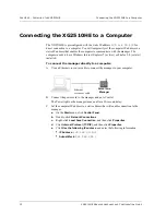
Page 18: ... To connect the manager directly to a computer A Use an Ethernet cross over cable to connect the manager to your computer B Connect the power cord to the manager and an AC outlet The Power light on the manager turns on after a 20 second delay C Set the computer IP address to a static address that will enable connection to the manager a On the Start menu click Control Panel b Double click Network C...

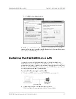
Page 19: ...2510HE gateway manager on a LAN you need to change the XG2510HE s default static IP address to a LAN IP address You can either configure the manager to use DHCP to obtain a LAN assigned IP address or assign a static LAN IP address to the XG2510HE If you want to use a static LAN IP address you will need to obtain this address from the LAN administrator To connect to the manager over the LAN A Use t...

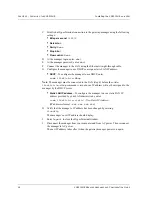
Page 20: ...nter sudo ifswitch to dhcp Note The manager must be connected to the LAN step 6 before the sudo ifswitch to dhcp command is issued or an IP address will not be assigned to the manager by the DHCP server Static LAN IP address To configure the manager to use a static LAN IP address provided by your LAN administrator enter sudo ifswitch to static New Static IP Address IP addresses format xxx xxx xxx ...

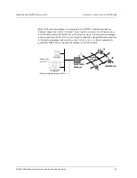
Page 21: ... or it will not receive a LAN IP address from the DHCP server If you power on or reset the gateway manager before connecting it to the LAN you will need to establish a HyperTerminal connection to the gateway manager and issue the sudo ifswitch to dhcp command to prompt the DHCP server to assign the manager a LAN IP address SmartMesh Manager Mote SmartMesh Network LAN WLAN Computer Ethernet straigh...

Page 22: ...CHAPTER 3 INSTALLING THE XG2510HE Installing the XG2510HE on a LAN 16 XG2510HE MANAGER HARDWARE AND CONFIGURATION GUIDE ...

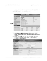
Page 23: ...adapter Note The Serial 1 interface is intended for local serial connections only Because no authentication is performed use it only in a trusted environment Using Admin Toolset to Configure Serial 1 To configure Serial 1 for PPP A Connect your computer to the XG2510HE gateway manager If the gateway manager is installed on the LAN connect your computer to the LAN If the gateway manager is not inst...

Page 24: ...Enter system as the username and the password E Click the Interfaces link F In the Interfaces Serial Port Settings area change the serial port settings if necessary If you are setting up a PPP connection enter the local and remote PPP IP addresses G Note By default the IP address of the manager over the PPP connection is 192 168 101 10 local IP address and the client PC s PPP IP address is 192 168...

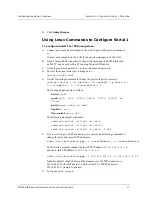
Page 25: ...y sudo set serial d device b speed p parity s stopbits f flow control The command options are as follows device ttyS1 speed 4800 9600 19200 38400 57600 115200 or 230400 parity none even or odd stopbits 1 or 2 flow control on or off The following are sample commands sudo set serial d ttyS1 b 38400 sudo set serial d ttyS1 b 115200 sudo set serial d ttyS1 b 38400 f off F If you are setting up a PPP c...

Page 26: ...APPENDIX A CONFIGURING SERIAL 1 OPERATION Configuring the Serial 1 Interface 18 XG2510HE MANAGER HARDWARE AND CONFIGURATION GUIDE ...

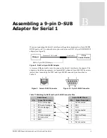
Page 27: ...example is a female RJ45 to female 9 pin D SUB The arrows indicate how to match up the RJ45 and 9 pin D SUB connector pins described in Table 11 Table 11 Matching Up RJ45 and 9 pin D SUB Connector Pins Manager PC or Control Device Crossover CAT 5 cable Serial cable RJ45 to 9 pin D SUB adapter Figure 10 9 pin D SUB Connector Figure 9 Female RJ45 Connector RJ45 Pinout 9 pin D SUB Pinout Pin Signal D...

Page 28: ...20 XG2510HE MANAGER HARDWARE AND CONFIGURATION GUIDE APPENDIX B ASSEMBLING A 9 PIN D SUB ADAPTER FOR SERIAL 1 ...

Page 29: ...ings Wireless network ID and common join key Access control list cleared Log files cleared Mote list cleared To restore the manager s factory default settings A Insert a jumbo paper clip into the Mode hole and gently press and hold down while you press and release the Power button Continue holding the paper clip down for another 20 seconds and then release The gateway manager s factory default set...

Page 30: ...r the default manager IP address 192 168 99 100 https 192 168 99 100 c If navigation to the site is blocked due to a certificate error click to continue on to the Web site the Web site is safe d In the Connect dialog box enter the following username and password Username system Password system e In the Admin Toolset window click the links in the left panel to view the default settings For example ...

Page 31: ...Mouser Electronics Authorized Distributor Click to View Pricing Inventory Delivery Lifecycle Information Murata XG2510HE ...

Reviews: