background image

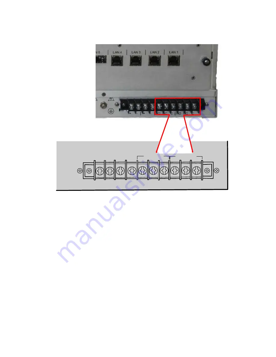
Alarm Relay Connections 


MAJOR

MINOR

NC

NO

C

NC

NO

C


The alarm relays on the unit will respond to alarm and alert conditions, the functionality can be 
programmed by the user as required and connected to their plant monitoring system.  Under normal 
operating conditions when the eXmux 3500M is turned on the relays are energized, in an alarm or 
alert state the relays will be in the de-energized position. 
 
Connect the Alarm Relays as required. 
 

Connecting Power 

 
The eXmux 3500M has labels located below the fuse on the power supply that indicate which 
power supply(ies) were installed in the unit before leaving the factory.  Main and redundant power 
supplies do not have to be the same.  
 
Before proceeding with the power and ground wire installation check the power supply labels to 
ensure that the unit will operate at the input voltage available. 


E

X

MUX 3500M Quick Start


RFL Electronics Inc. 

January 23, 2013 

                         3 

973.334.3100 

Summary of Contents for eXmux 3500

Page 1: ...ed to get the user up and running quickly after receiving their eXmux 3500M IP Access Multiplexer These instructions are not to be used as a substitute for the RFL Instruction Manual Please refer to t...

Page 2: ...edundant power supply switches are in the OFF position and that the power wires to be installed are disconnected at their source All relay contacts are labeled in the de energized position Ensure that...

Page 3: ...relays will be in the de energized position Connect the Alarm Relays as required Connecting Power The eXmux 3500M has labels located below the fuse on the power supply that indicate which power supply...

Page 4: ...put power Improper ground connections may result in system malfunctions equipment damage or electrical shock Grounding is accomplished by connecting a 6 AWG wire or larger between the protective earth...

Page 5: ...ar eXmux 3500M Input power connections can be either 24 Vdc 48 125 Vdc 250 Vdc from a station battery 120 or 220 Vac depending on which power supplies are installed in the unit Make the required conne...

Page 6: ...allation note the following The eXmux 3500 Visual NMS software is conveniently loaded into the user s laptop or PC through the supplied CD Part MCD3500 XXX or downloaded from the RFL website at www rf...

Page 7: ...Visual NMS 3 In another Windows Explorer window navigate to Computer Local Disk C Program Files Exmux 3500 Visual NMS Drag and drop the entire data folder into the folder created in step 2 The result...

Page 8: ...operating system and Windows XP Operating System XP service pack 2 or above other Windows systems will be similar Currently RFL supplies a USB Driver for Windows7 32 and 64 bit operating system users...

Page 9: ...ow the steps below Note there are two parts to this configuration process The USB Interface and the USB Serial Port both parts MUST be completed to correctly configure the USB Driver Double click on E...

Page 10: ...the Driver Software is located on your computer Ensure this box is checked Select the USB Driver and click Next Select Install this driver software anyway Select Select Select Update Driver Click Clo...

Page 11: ...ey do not return to the Devices and Printers dialog as shown below and double click on Exmux 3500 USB Interface Select the Hardware tab Double click Now proceed to the following page to configure the...

Page 12: ...re the Driver Software is located Ensure this box is checked Select the USB Driver and click Next Select Install this driver software anyway The USB Interface has been successfully installed Double cl...

Page 13: ...yway Click Finish The dialogs may run twice follow the previous screen instructions The USB Interface has been successfully installed Double click the exmux 3500 User Access USB icon on your desktop t...

Page 14: ...t the eXmux 3500M will be in Minor Alarm until the default Admin_Passwd1 password is changed The password must be between 10 and 32 characters in length and MUST contain a character from each of the f...

Page 15: ...h 7 The default Multicast Address is 224 192 16 2 change as necessary The default Node ID is 0 The Node ID can be set between 1 and 999 The Node ID can also be assigned automatically by the VNMS softw...

Page 16: ...tivate the eXmux 3500 Visual Network Management Software VNMS Before entering the Key Code note the following In a situation where both the eXmux and PC are connected to the same network configuring f...

Page 17: ...d Internet Protocol TCP IP is highlighted 4 Click the Properties button the following dialog box will open Check this button This information can be ignored 1 2 Add IP information here 3 Check OK EXMU...

Page 18: ...asis The following dialog box will appear Type control into the User ID field and password into the Password field and check the Log In button After logging in to VNMS you may want to change the User...

Page 19: ...the eXmux 3500 IP Access Multiplexer Title Part Number eXmux 3500 VNMS Software and Documentation MCD3500 XXX VNMS Software Install application Instruction Manual pdf bundled with VNMS Document Revis...

Page 20: ...this publication does not constitute a warranty of performance RFL Electronics Inc reserves the right to revise this publication and make changes to its contents from time to time We assume no liabili...

Reviews: