Page 18
3 Cap
Screws
FIGURE 25 - Split Taper
Bushing
2 Push-Off Holes
Motor and Belt Shipping Position for Sizes 2-80, 2-120, 3-180, 3-260 - To
relieve tension on the motor mounting bracket, the belt(s) are taken off the
motor and blower sheaves before shipping. The belt(s) are taped to the blower
shaft to prevent loss or damage during shipment. Install the belt(s) and adjust
for proper belt tension.
Blower Pulley - Size 2-80 and 2-120 systems equipped with 3 and 5 HP mo-
tors with a 15.4" diameter and larger blower pulley or a 7-1/2 HP and larger
motor and all Size 3-180 and 3-260 systems are equipped with a split taper
bushing in the blower pulley. The split taper bushings must be loosened in
order to remove the pulley. Follow these instructions to loosen the bushing.
1) Notice that there are three cap screws in the bushing and two holes
without screws, called push-off holes (See FIGURE 25).
2) Remove the three cap screws.
3) Put two of the cap screws into the two push-off holes. Tighten these two
screws evenly until the pulley is loosened.
4) Pulley may now be removed from the shaft.
Blower Speed Adjustment - Units are set at the factory for the RPM required
to meet the CFM and external static pressure specified on the order. If the
estimated external static is incorrect, or changes are made to the duct system,
the blower RPM may have to be changed. Motors are equipped with adjust-
able pitch pulleys which permit adjustment of blower speed. Instructions are
included in Paragraph 13, Check-Test-Start for adjusting blower speed.
Blower Rotation - Each blower housing is marked for proper rotation. In-
structions for checking blower rotation are included in the Check-Test-Start
Procedure in Paragraph 13.
Motor Loads - Use an ammeter to check motor amps. Amps may be adjusted
downward by reducing blower RPM or by increasing duct system static pres-
sure. For accurate amps, read the motor manufacturer's rating plate; amps will
vary depending upon motor manufacturer. The chart below can be used for
sizing line wiring.
Gas Pressure
Switches
High gas pressure switches included in the gas train monitor gas pressure
downstream from the safety valves. If the gas pressure at this point on a sys-
tem equipped with a high gas pressure switch (standard with Manifolds BM
78, 79, 80, and 81 or Option BP2 with other manifolds) exceeds the setpoint,
the switch will open the electrical circuit to the burner, stopping all gas flow.
The high gas pressure switch is a manual reset device.
A low gas pressure switch (Option BP3) will shutoff the gas flow if the gas
pressure drops below the setpoint of the low pressure switch. The low gas
pressure switch will automatically reset when the gas pressure rises above the
setpoint.
(NOTE: Model RDF units manufactured prior to April 1993 installed indoors
with optional gas pressure switches require a 3/4" vent line to the outdoors.
Beginning with units manufactured April 1993, the gas pressure switches in-
corporate a vent limiting device and do not require venting to the outdoors.)
12. Blowers,
Drives, and
Motors
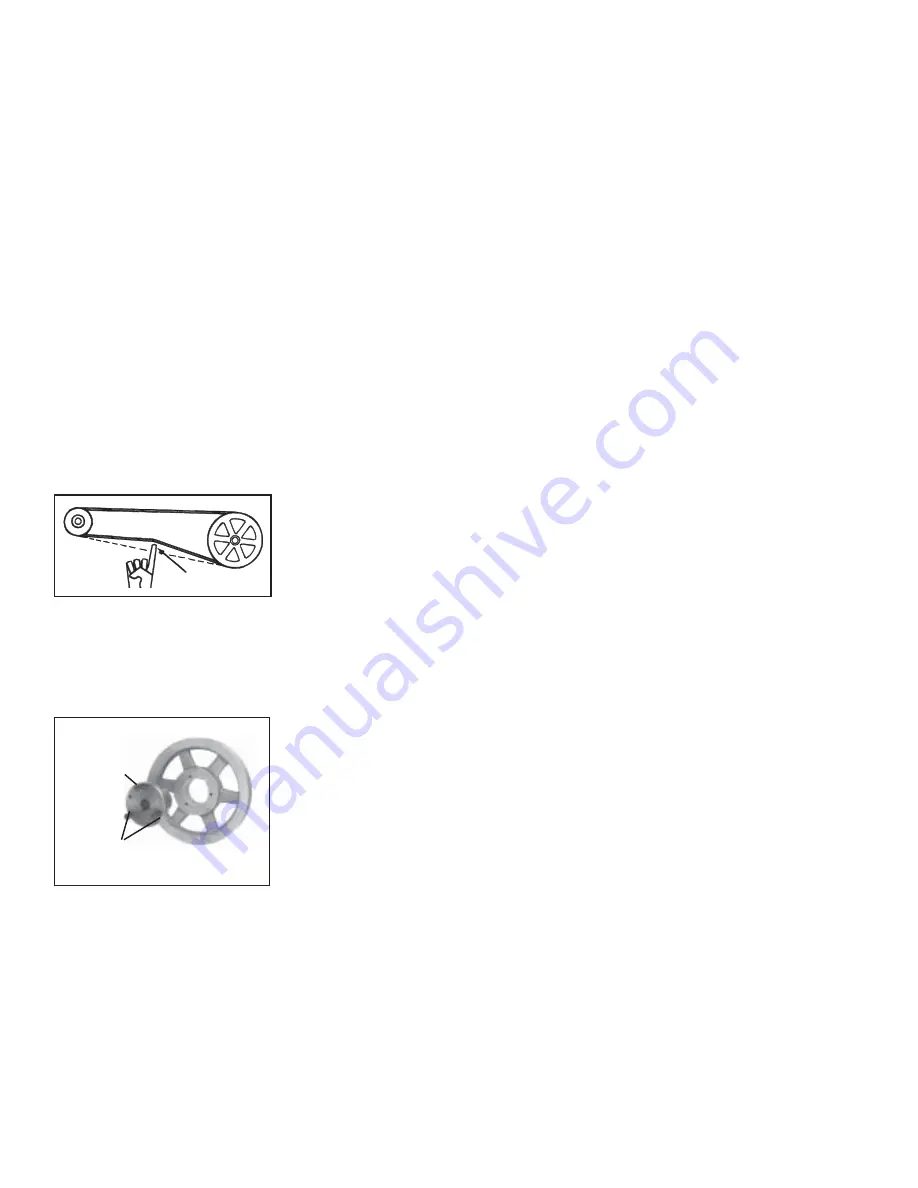
Belt Tension - Check belt tension. Proper belt tension is important to the long
life of the belt and motor. A loose belt will cause wear and slippage. Too much
tension will cause excessive motor and blower bearing wear. If adjustment is
required, adjust belt tension by means of the adjusting screw on the motor
base until the belt can be depressed 1/2" to 3/4" (FIGURE 24). Tighten the
lock nut on the adjusting screw. Be sure the belt is aligned in the pulleys.
3/4 (19mm)
FIGURE 24 - Belt Tension
11. Gas Piping
and
Pressures
(cont'd)


