24
Example:
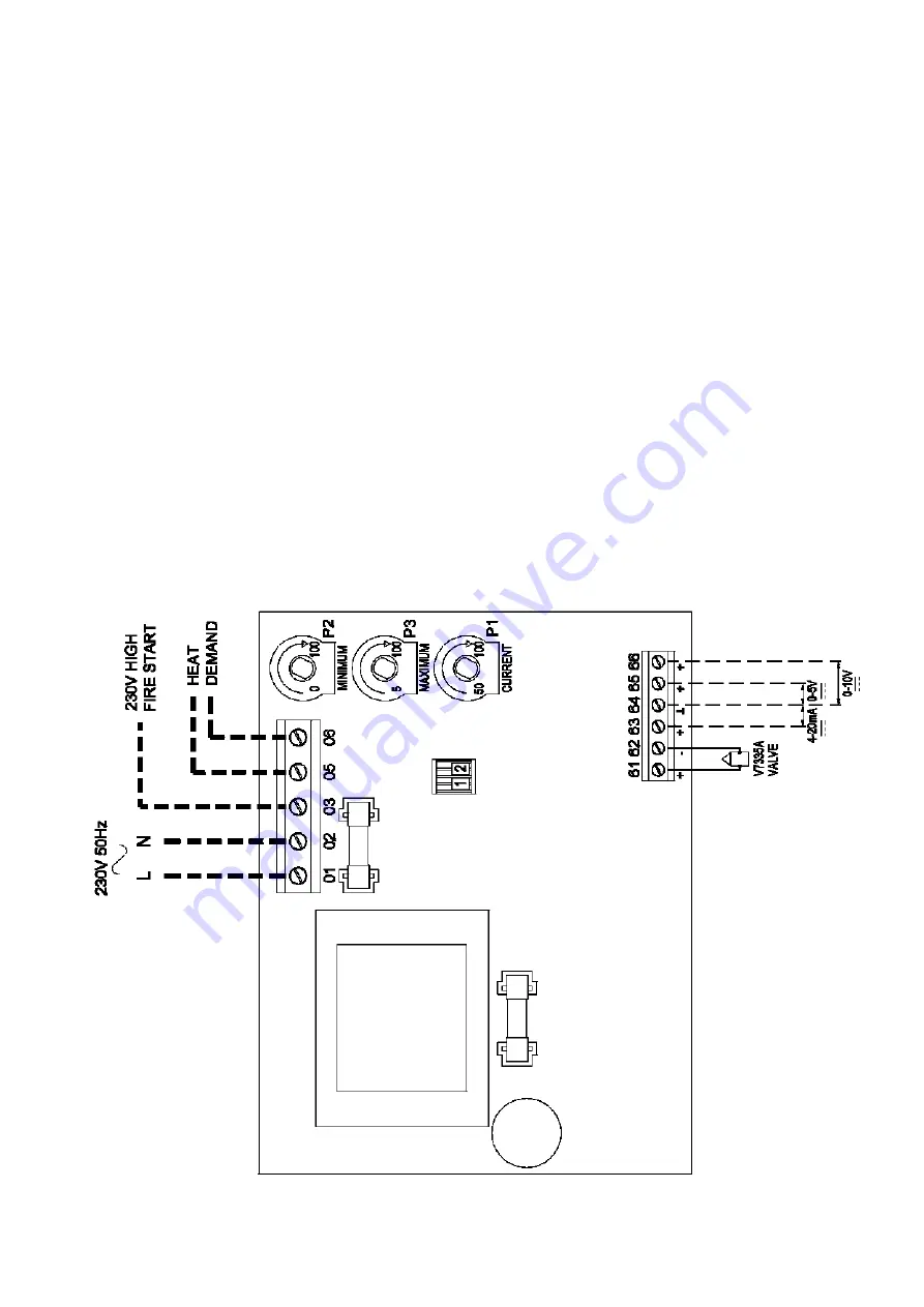
Potentiometer P2 is set at 0 %, and P3
at 5%, the hold-in voltage of the
burner relay is adjustable between 5
% and 100 % of the input control
signal. So, if input control signal is set
at 0 to 10V DC, the hold-in voltage of
the relay amounts to 0.5V DC.
Potentiometer P2 is set at 40 %and P3
at 5%, the hold-in voltage of the
burner relay is adjustable between 45
%and 100 % of the input control
signal. So, if the input control signal is
set at 0 to 10 VDC: the hold-in voltage
of the relay amounts 4.5V DC.
Adjustment of the current control.
Potentiometer P1
The control current or voltage of one or two
Honeywell modulation coils GM44 is
controlled by the potentiometer PI, varying
between 50 % and 100 % of the input
control signal.
Example:
Maximum power (165
mADC
at 22V
DC) is provided to the modulation coil
with a 10V DC input control signal and
P1 set at 100 %
Maximum power (165mA-DC at 22V
DC) is provided to the modulation coil
with a 5V DC input control signal and
potentiometer PI set at 50 %.
High fire start signal
A maximum control current or voltage is sent
to the modulation coil for 10s when a 230V
AC line input voltage appears on terminal 3.
This 230V AC line input voltage is generated
by a contact in the burner relay incorporated
within the appliance.
When opening the main gas valve and when
ionisation current is sufficient, the 230V AC
line input voltage is directed towards
terminal 3 of the interface board.


