Appendix B • Falk Quadrive Shaft Mounted Drives Model A
(Page 32 of 52)
Sizes 5107-5315
378-200
(PN-2128394)
Rexnord
January 2019
3001 W. Canal St., Milwaukee, WI 53208-4200 USA
Supersedes 04-17
Telephone:
414-342-3131
Fax:
414-937-4359
www.rexnord.com
Backstop Installation
INTRODUCTION
The following instructions apply to INSTALLATION ONLY
of internal backstops in horizontal drives, sizes 5107 thru
5215 single and double reduction and size 5307 & 5315
double reduction
CAUTION:
If backstop is to be replaced, the high-speed
shaft must also be replaced. Refer to instructions regarding
high-speed shaft replacement, Section III.
Remove all external loads from system before servicing drive
or accessories, and lock out starting switch of prime mover
LUBRICANT
PETROLEUM-BASED LUBRICANTS —
Use R & O type
lubricants which do not contain extreme pressure (EP)
additives if the drive is equipped with an internal backstop
CAUTION:
Do not use EP lubricants, or lubricant
formulations including sulfur, phosphorus, chlorine, lead
derivatives, graphite or molybdenum disulfides in drives
equipped with internal backstops. Refer to Appendix A
for proper selection of lubricants. Use of an improper
lubricant will contribute to premature wear or malfunction
of the backstop.
SYNTHETIC LUBRICANTS —
Synthetic lubricants of the
polyalphaolefin type may be used in drives with internal
backstops
Before installing backstop, check direction of free rotation
(overrunning) indicated by the arrow etched on each side
of the backstop
BACKSTOP APPLICATION
Backstops are designed to prevent reverse rotation
or back-run without backlash in applications such as
conveyors, bucket elevators, fans, rotary pumps and
kilns Backstops are not approved for use on systems that
are designed for handling of people such as elevators,
manlifts, ski tows and ski lifts DO NOT use a backstop as a
substitute for a brake
INDEXING
DO NOT use the backstop for indexing applications
The backstop is designed to prevent reverse rotation
five times or less in eight hours, with one minute or
more in overrunning direction between backstopping
load applications If backstopping operations are more
frequent, or the time between operations is less than one
minute, the backstop is classified as an indexing device
and must be referred to the Factory
INSTALLATION
(Backstop Added to Existing Drive
Only)
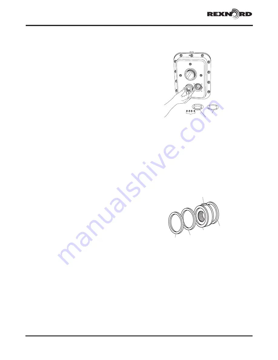
1 DRIVE PREPARATION: Drain oil from drive Remove
fasteners Ref #27, end cover Ref #23, and gasket Ref
#16, Figure 1 Keep size 5115J and 5207J end covers,
size 5207J fasteners and all lock washers for reuse, all
other parts may be discarded
REF. #23 GASKET
REF. #16
SHAFT COVER
REF. # 27
FASTENERS
Figure 1
2
BACKSTOP PREPARATION:
Remove backstop Ref
#5A1 from the kit and wipe off any excess lubricant
On drive sizes 5107 (all ratios) and 5115 (24 87 ratio),
assemble retaining ring Ref #5A2 onto one of the
grooves on the backstop OD On drive size 5115J25,
assemble spacer Ref #5A6 to backstop OD adjacent
to retaining ring on inboard side All other size 5115J
and larger drives, insert housing spacer Ref #5A3
(retaining ring used as housing spacer on drive size
5207J) into housing bore adjacent to bearing cup
(Figure 2) Assemble key Ref #5A4 to backstop keyway
(spacer Ref #5A6 is between retaining ring and key on
511J25 backstop)
REF.# 5A4
5A2
DRIVE SIDE
REF.# 5A1
REF.# 5A6
SHAFT
COVER
SIDE
(5115J25 ONLY)
REF.# 5A3 SPACER
REF.#
3
ALL SIZES — BACKSTOP INSTALLATION:
Apply oil
to the O D of the high-speed shaft backstop journal
and the sprags inside of the backstop Align the
backstop key with the keyway in the exposed housing
bore and carefully slide the backstop into the bore
while slowly rotating the high-speed shaft The shaft
will only rotate in one direction DO NOT FORCE OR
HAMMER; this may damage the shaft or misalign the
sprags
Check operation of backstop by turning high-speed
shaft in required direction of rotation by hand If the
shaft does not rotate in the required direction, remove
backstop, reverse it, reposition the retaining ring and
spacer (where used) and reinsert it into the housing
bore as instructed
Figure 1


