Falk Quadrive Shaft Mounted Drives Model A • Owners Manual
Sizes 5107-5315
(Page 13 of 52)
Rexnord (PN-2128394)
378-200
3001 W. Canal St., Milwaukee, WI 53208-4200 USA
January 2019
Telephone:
414-342-3131
Fax:
414-937-4359
www.rexnord.com
Supersedes 04-17
7
SEAL INSTALLATION
CAUTION:
Protect seal lips from sharp edges of
the keyway by wrapping thin, strong paper around
the shaft and coating the paper and seal lips with
grease before sliding the seal on or off the shaft Do
not expand the seal lips more than 030” (0 75 mm)
diameter
.
a Coat O D of seal with #3 Permatex or equivalent
sealant Position seal squarely in seal bore with
the garter spring toward bearing Place a square
ended cylindrical tool against seal and press or
lightly tap tool (not seal) until seal outer wall is
seated 14” (3 5 mm) inside the seal bore outer
wall
CAUTION:
A shaft shoulder is NOT provided for
stopping seal. DO NOT seat seal against bearing.
b Measure seal axial run-out with a dial indicator
mounted on the shaft If the seal axial run-out is
more than 010” (0 25 mm), tap high side of seal
with installation tool until seal axial run-out is 010”
(0 25 mm) or less
c Remove shaft wrapping and reinstall the input side
seal covers, Ref #13 and 15
8
DRIVE REPAIR IS COMPLETE —
Review instructions
in Section I for reassembly of drive onto driven shaft
9 When seals, Ref #19 & #20, are to be reused
(replacement is recommended), wrap the input shaft
keyway and output shaft threads with masking tape
or lightweight Kraft paper to protect seal lips during
disassembly Cover wrapping with a light coat of
grease
10 If drive is equipped with a backstop, remove output
side end cover Ref #16, gasket Ref #23, backstop
Ref #5A1, and key Ref #5A4 from output housing Ref
#11 (note the direction of rotation of the input shaft for
proper reassembly)
11 Lay drive on bench with input shaft down Remove
housing flange fasteners, Ref #25 Tap out dowel pins
SIZE 5115J05 —
Remove fasteners from retaining
plate, Ref #3A6
SIZES 5203 THRU 5315 —
Use one of the housing
flange fasteners as a jackbolt to separate input and
output housing halves using the tapped hole on input
housing flange provided for this purpose Carefully lift
off output housing, Ref #11
12 Remove the shaft assemblies (J05 - 3A & 4A; J09, J14
or J25 -1A, 2A, & 4A) from input housing, Ref #10
13 Drive seals out from input and output housing bores
if replacement is indicated Remove gasket material,
seal compound and any accumulated foreign matter
from seal joints, bores and adjacent sealing surfaces
Use a solvent to clean housing and shaft assemblies
CAUTION:
On sizes 5203 thru 5315, tapered roller
bearing cups are assembled in input housing with
a slight clearance fit. In addition, metal shims for
adjusting bearing preload and axial float are installed
behind bearing cups in housing. When handling input
housing, be careful that bearing cups and shims do
not fall out of input housing.
14 If drive is equipped with a backstop, check the shaft
surface and backstop sprags (inside diameter) for
signs of wear If either component shows evidence
of wear, both should be replaced (Ref #1A and 5A or
Ref #3A and 5A assemblies) Also refer to Step 6 for
inspection of seal surfaces
15 Inspect gear teeth for wear or indications of fatigue
e g hairline cracks at root of tooth If one element has
undergone severe wear or broken teeth, replace the
mating element also
16 Clean and inspect bearings for wear Lubricate with
light oil before spinning to avoid scoring of working
surfaces Remove any worn bearings with a wheel
puller When replacing tapered roller bearings,
replace both cups and cones DO NOT use new cone
assemblies with worn (old) cups
17 Use a wheel puller or press to remove gears Ref
#1A4 or 4A4 from the shaft Exercise caution to avoid
scoring shaft seal diameter with the keyway of gear
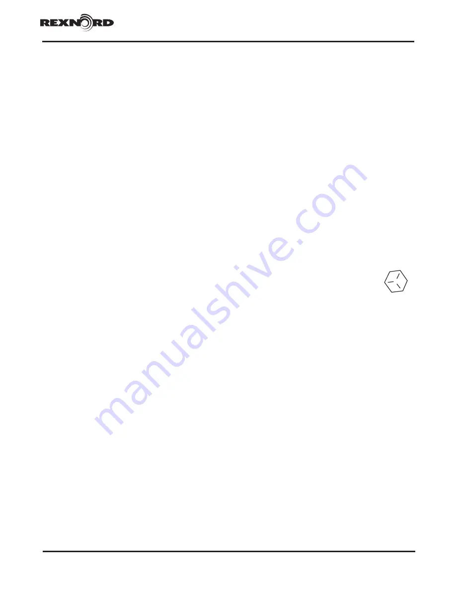
18 Inspect all fasteners for damage or wear and replace
with fasteners of equal grade Grade 5
fasteners have three (3) radial lines on the
head Fasteners are available in kit form,
Ref #80
19 If the shaft assemblies can be reused intact (no new
parts required), refer to Section III, Steps 6 thru 9, for
reassembly procedure Replace all shim-gaskets with
new parts, Kit Ref #100 On sizes 5107 and 5115, use
the same thicknesses as removed during disassembly


