


Owners Manual
•
Falk
™
Drive One
®
Enclosed Gear Drives
(Page 6 of 27)
Type D Series
•
Sizes M1130 thru M1210
168-050
Rexnord Industries, LLC, 3001 W. Canal St., Milwaukee, WI 53208-4200
January 2019
Telephone: 414-342-3131 Fax: 414-937-4359
Supersedes 04-11
e-mail: [email protected] web: www.rexnord.com
(PN 2124650)
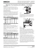
OFFSET ALIGNMENT
— Align
driving and driven shafts so that
a straight edge will rest squarely
on both couplings hubs as
shown to the right and also at
90° intervals. Tighten foundation
bolts of the connected
equipment and recheck
alignment and gap.
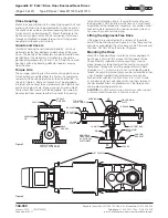
SPROCKETS, PULLEYS OR SHEAVES
— Mount power
take-offs as close to the gear drive housing as possible to
avoid undue bearing load and shaft deflection.
Align the output shaft of the gear drive square and parallel
with the driven shaft by placing a straightedge across the
face of the sprockets or sheaves as illustrated.
Check horizontal shaft alignment
by placing one leg of a square
against the face of the sheave or
sprocket with the spirit level on the
horizontal leg of the square.
DO NOT over tighten belts or chains. Adjust chains to
manufacturers’ specifications. Adjust belts as follows:
The ideal tension is the lowest tension at which the belt
will not slip under peak load conditions. Check the belt
tension frequently during the first 24 to 48 hours of run-in
operation. Over tightening belts shortens belt and bearing
life. Keep belts free from foreign material which may cause
slippage. Inspect the V–belt periodically; tighten the belts
if they are slipping.
OUTBOARD BEARING
— Mount the outboard bearing and
gear drive on a common foundation so that they will shift
as an assembly if settling should occur. Bring the outboard
bearing to the correct horizontal position with broad flat
shims under the mounting pad. Align accurately so that
the load is equally divided between the two drive bearings
and the outboard bearing. Mount a stop bar against the
pillow block foot on the load side when large horizontal load
components are exerted on the pillow block.
PINION MOUNTING
— Mount pinion as close to the
drive as possible to avoid undue bearing load and shaft
deflection. Refer to the Factory for pinion alignment
instructions.
NON FALK COUPLINGS
— Refer to manufacturers’
installation and maintenance instructions.
BACKSTOPS
— To prevent damage to backstops due to
incorrect motor shaft rotation at start up, couplings are NOT
assembled when gear drives are furnished with backstops.
After completing electrical connections, check motor and
gear drive shaft rotations. If rotations are correct, complete
alignment and assembly of coupling.
Steelflex Illustrated
RIGHT
WRONG
LEVEL
GEAR DRIVE WALL
SQUARE AND
PARALLEL
Fastener Tightening Torques
Use the tightening torque values specified in Table 4 for
fastening Falk gear drives, motors and accessories to their
mounting surfaces with un-lubricated fasteners. DO NOT use
these values for “torque locking” fasteners or for fastening
components with aluminum feet or soft gaskets or vibration
dampeners on the mounting surface. If the tightening torque
exceeds the capacity of the torque wrench, use a torque
multiplier. Use ISO property class 8.8 for metric fasteners. See
Table 12 for fastener and wrench size.
Table 4 — Tightening Torques: ±5%
DO NOT Lubricate Fasteners
Metric Fasteners – Property Class 8.8
Fastener
Size
Metal to Metal
Metal to Concrete
Nm
lb-ft
Nm
lb-ft
M4 x .7
3
2
2
1.5
M5 x .8
6
5
5
3.5
M6 x 1.0
10
8
8
6
M8 x 1.25
24
18
19
14
M10 x 1.5
50
36
39
29
M12 x 1.75
84
62
68
50
M16 x 2
210
156
170
126
M20 x 2.5
415
305
330
246
M24 x 3
705
530
570
420
M30 x 3.5
1 440
1060
1 150
850
M36 x 4
2 520
1860
2 030
1500
M42 x 4.5
4 050
3000
3 250
2400
M48 x 5
6 100
4500
4 880
3600
M56 x 5.5
9 850
7300
7 860
5800
Water Cooling
WATER COOLED HEAT EXCHANGERS
— Install a shut-
off or control valve in the water line to the heat exchanger
to regulate the water flow through the exchanger. Also
install a water flow gauge between the control valve and
the exchanger to determine actual flow rate. Discharge
water to an OPEN DRAIN to prevent back pressure.
INTERNAL COOLING TUBES
— Refer to Appendix E for
installation, operation, and maintenance of internal cooling
tubes.
Lubrication Systems
SPLASH LUBRICATED DRIVES
— Standard horizontal
shaft type DH & DB drives are splash lubricated. The
lubricant is picked up by the revolving elements and
distributed to the bearings and gear meshes.
OIL PUMP LUBRICATED DRIVES
— Types DV and DX
are equipped with an external oil pump to provide oil
to the upper bearings and gear meshes. The system is
composed of an electric motor-driven gear pump and
an internal distribution network with relief valve (set at
30 psi). The pump system may be furnished with a 50 or
60Hz, 3-phase electrical motors based on the selection.
Refer to the pump motor nameplate and Table 5 for
electrical requirements. Wire the motor for correct rotation
as indicated by the rotation arrow. Optional accessories
include an oil filter and flow indicator with switch. The flow
indicator has a single pole, double throw switch rated at
15A, 125V/7A, 250V maximum. Connect the flow indicator
switch with the prime mover control circuitry to prevent
drive operation without the lubrication system.
Other types of gear drives may also be equipped with oil
pumps for special lubrication considerations or external
cooling.