


Appendix D
•
Falk
™
Drive One
®
Enclosed Gear Drives
(Page 20 of 27)
Type D Series
•
Sizes M1130 thru M1210
168-050
Rexnord Industries, LLC, 3001 W. Canal St., Milwaukee, WI 53208-4200
January 2019
Telephone: 414-342-3131 Fax: 414-937-4359
Supersedes 04-11
e-mail: [email protected] web: www.rexnord.com
(PN 2124650)
Close Coupling
Mount the coupling hubs to the drive high-speed shaft and
motor shaft. Hubs are to be mounted flush with the end of
the shafts unless otherwise noted (coupling hubs may be
furnished with an interference fit). Mount the motor to the
bell housing, apply Loctite #242 or equivalent to fastener
threads and tighten to proper torque. Install high-speed
coupling per coupling instructions.
Guards and Covers
Install bell housing covers (top and bottom). Install air
deflectors on the top, bottom and both sides of the gear
drive. The bends of the deflectors are perforated to allow
positioning of the deflectors. Air deflectors should be
positioned approximately 25 mm (1 inch) from the nearest
housing surface by bending deflector towards or away
from the drive.
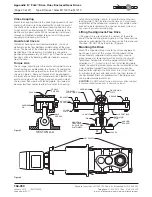
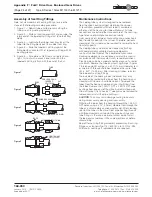
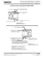
Torque Arm
The carriage, adjusting rod, brackets and support bar are
furnished pre-assembled from the Factory. Assemble the
rod ends with heads perpendicular to each other (90°) as
shown in Figure 3. Rod end threads must be engaged a
minimum of one times thread diameter. Attach female rod
end to carriage with pin. Place a spacer on each side of
the rod end. Secure pin with locking plate. Carriage may
be adjusted from center to either far end of the housing
to facilitate installation of pin. Ensure that adjusting rod
locking plate is NOT installed at this time as it will prevent
adjustment of the torque arm assembly. Assemble anchor
bracket to male rod end with a spacer on each side and
secure with pin and retaining ring.
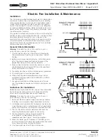
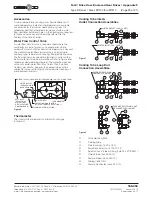
Lifting the Alignment-Free Drive
Lifting points are provided on the corners of the motor
end of the bell housing. See Figure 4. Lift by these and the
provisions provided on the drive housing itself to maneuver
the drive. DO NOT lift by the motor lifting eye.
Mounting the Drive
Mount the Alignment-Free drive to the driven equipment
per Pages 2 and 3 of this manual. With Alignment-Free
drive assembly supported, rotate adjusting screw to
move torque arm to desired position and to line up with
foundation. Torque Arm must be perpendicular in both
directions (± 1°). Adjust screw if not. Install locking plate
to lock the adjusting screw (plate can be installed on either
side). Remove support from drive and secure anchor
bracket to foundation. Use M24 Class 8.8 (1 inch Grade
5) or better fasteners with lock and flat washers to mount
anchor bracket. Slots are provided such that torque arm
can be mounted perpendicular.
CAUTION
: Do NOT adjust torque arm screw after support
is removed and torque arm is under any load.
A
CARRIAGE
PIN
SPACER
FEMALE
ROD END
MALE
ROD END
SECTON A-A
THREADED
ADJUSTING ROD
BRACKET
ADJUSTING
SCREW
LOCKING
PLATE
CARRIAGE
PIN LOCKING
PLATE
BRACKET
SUPPORT BAR
RETAINING
RING
ANCHOR
BRACKET
SPACER
MOUNTING
HARDWARE
(SUPPLIED BY
CUSTOMER)
PIN
JAM NUT
A
Figure 3
LIFT POINTS
Figure 4