


Owners Manual
•
Falk
™
Drive One
®
Enclosed Gear Drives
(Page 2 of 27)
Type D Series
•
Sizes M1130 thru M1210
168-050
Rexnord Industries, LLC, 3001 W. Canal St., Milwaukee, WI 53208-4200
January 2019
Telephone: 414-342-3131 Fax: 414-937-4359
Supersedes 04-11
e-mail: [email protected] web: www.rexnord.com
(PN 2124650)
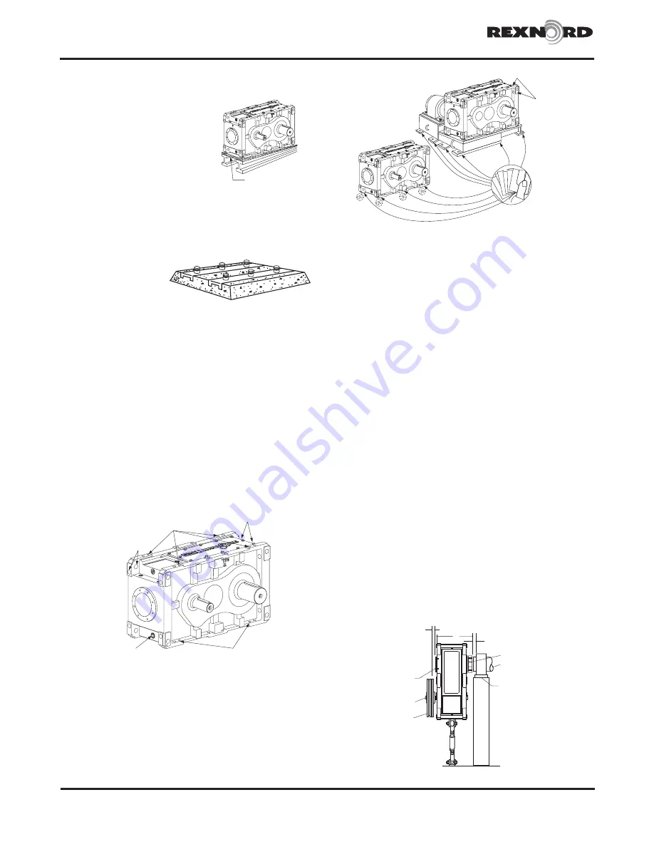
FOUNDATION, STEEL
— When mounting gear drive on
structural steel, it is recommended that an engineered
design be utilized for a pedestal,
adapter base or bed to provide
sufficient rigidity, to prevent
induced loads from distorting
the housing and causing gear
misalignment. In the absence
of an engineered design, it is
recommended that a base plate,
with thickness equal to or greater
than the thickness of the drive
feet, be securely bolted to steel supports and extend
under the entire drive as illustrated.
FOUNDATION, CONCRETE
— If a concrete foundation is
used, allow the concrete to set firmly before bolting down
the gear drive. For the
best type of mounting,
grout structural steel
mounting pads into
the mounting base, as
illustrated, rather than
grouting the drive directly into the concrete.
Motors and other components mounted on motor plates or
motor brackets may become misaligned during shipment.
ALWAYS check alignment after installation. Refer to page 5
for coupling alignment instructions.
Gear Drive Alignment
FOOT-MOUNTED DRIVES
– Align drive with driven
equipment by placing broad, flat shims under all mounting
pads. Jack screw holes are provided by mounting feet to
facilitate alignment. See Table 12, page 10 for fastener
and wrench sizes. Start at the low-speed shaft end and
level across the length and then the width of the drive.
Check with a feeler gauge to make certain that all pads are
supported to prevent distortion of housing when drive is
bolted down. After drive is aligned with driven equipment
and bolted down, align prime mover to drive input shaft.
Refer to page 5 for coupling alignment.
CONTINUOUS PLATE
LIFTING HOLES
2 PER CORNER
(16 TOTAL)
JACKING
SCREW HOLES
DIPSTICK/VENT
HOLES
JACKING
SCREW HOLES
DRAIN
PLUG
If equipment is received from the Factory mounted on
a bedplate, the components were accurately aligned at
the Factory with the bedplate mounted on a large, flat
assembly plate. Shim under the bedplate foot pads until
the gear drive is level and all feet are in the same plane.
Check high-speed shaft coupling alignment. If the
coupling is misaligned, the bedplate is shimmed
incorrectly. Re-shim bedplate and recheck high-speed
coupling alignment. If necessary, realign motor.
Shaft-Mounted Drives – General
Shaft-mounted drives should never be mounted in a
manner that restricts the natural movement of the drive.
They should be allowed to move freely with the shaft on
which it is mounted. Shaft-mounted drives should always
be used in conjunction with a torque reaction arm. Refer
to Appendixes A, B or C for torque reaction arm mounting
instructions and angular limits. The drive may require
repositioning on the driven shaft after initial installation to
accommodate the location of the foundation anchor and
be within limits specified in Appendix A (fixed torque arm)
or Appendix B (adjustable torque arm).
The tapered bore hollow shaft is designed for use with a TA
Taper
®
bushing for mounting the drive on a driven shaft
with a straight outside diameter. The taper bushing
assembly is supplied with a thrust plate kit and retention
fastener as standard (usage is optional, shaft cover must
be removed to install thrust plate kit). Refer to data sheet
supplied with the tapered bushing assembly for driven
shaft length, shaft keyway length and driven shaft tapped
hole dimensions if the thrust plate kit with retention
fastener is to be used.
Prior to installing the drive, it is a good idea to check
the driven shaft for proper dimensions. Using Table
1 or 1A, find the driven shaft size for the application.
Verify that dimensions A and B are within the allowable
range. When dimensions are verified, proceed with the
installation. The minimum and maximum driven shaft
engagements, dimension N in Figure 1, are shown in
Table 2. The minimum engagement is necessary for full
bushing engagement, and the maximum (and specified)
engagement is provided for use when the thrust plate kit is
used for added retention capacity and an auxiliary removal
aid (bushing nut normally used for both).
LEVELING
REFERENCE
SURFACES
SHIMS
KEEP CLOSE
KEEP CLOSE
BUSHING NUT
DRIVEN SHAFT
BEARING
SUPPORT
THRUST
PLATE
BORE
INPUT
SHAFT
SHEAVE
N
Figure 1