Falk
®
CT-Series Gear Drives • Operation and Maintenance
Sizes 2160 thru 2400
(Page 7 of 7)
Rexnord
GR3-014
3001 W. Canal St., Milwaukee, WI 53208-4200
January 2017
Telephone: 414-937-4359 Fax: 414-937-4359 www.rexnord.com
NEW
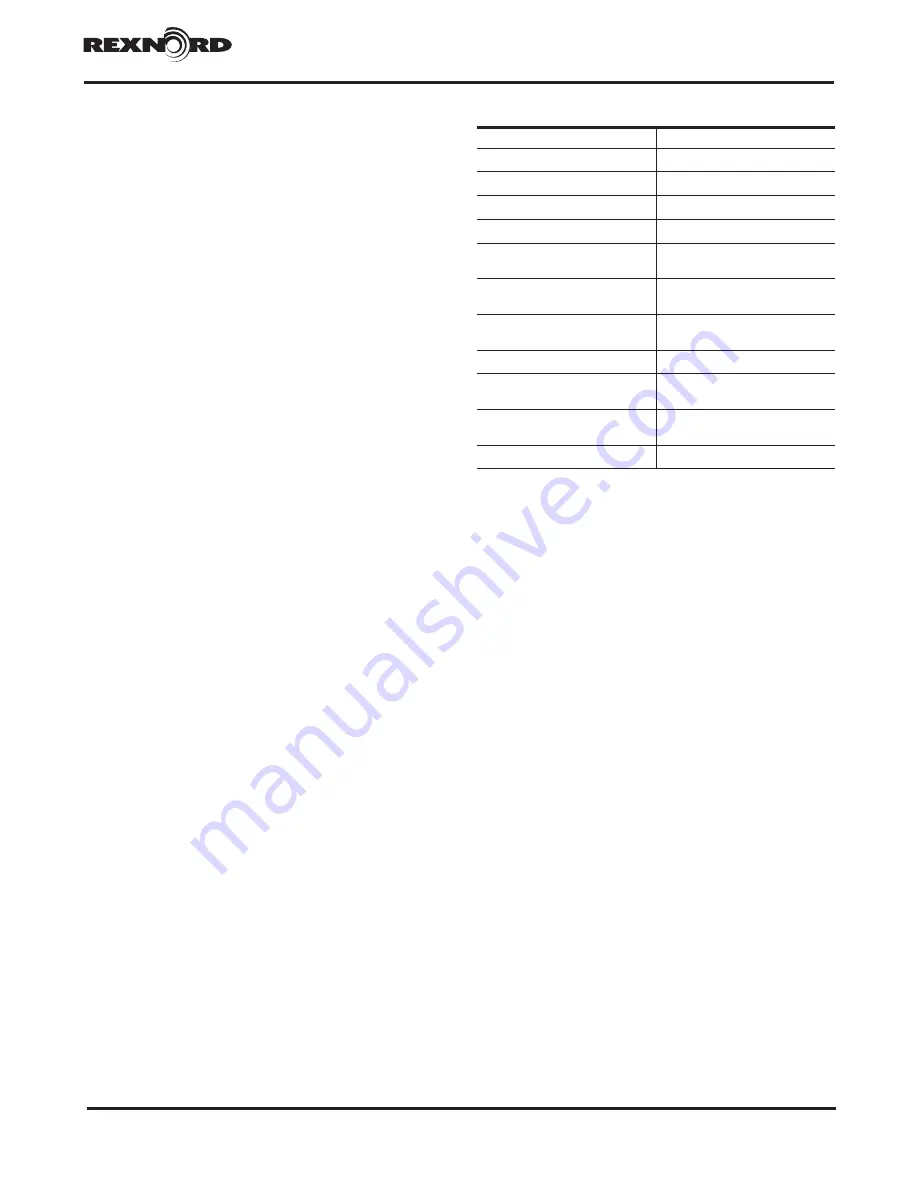
Table 2 — Maintenance
Measure
Period
Check the oil temperature
Daily
Check for unusual gear-unit noise
Daily
Check the oil level
Monthly
Check the gear unit for leaks
Monthly
Test the water content of the oil
After approx. 500 operating hours,
at least once per year
Perform the first oil change
Approx. 200 operating hours after
start-up
Perform oil changes
After every 1500 to 5000 operating
hours
Clean air filter
Every 3 months
Clean the gear unit
Depending on requirements, at
least every 2 years
Check tightness of screw
connections
After first oil change, then every
2 years
Inspection of the gear unit
Approx. every 2 years
8.2 CLEAN THE BREATHER PLUG
If a layer of dust has built up, the breather plug must
be cleaned, whether or not the minimum period of 3
months has expired.
Unscrew the breather plug including the reducing
screw.
Clean the breather plug using benzene or a similar
cleanser.
Dry the breather plug.
8.3 TOP UP OIL
The instructions in item 7.1 must be observed!
Always top up with the same type of oil as already
used in the unit (see also item 8.1).
8.4 CHECK TIGHTNESS OF SCREW CORRECTIONS
The instructions in item 8.1 must be observed.
Close the stop valves in the coolant in- and outflow
pipes (for gear units with water oil-cooling system).
Check tightness of all screw connections.
8.5 GENERAL NOTES ON MAINTENANCE
All maintenance and repair work must be done with
care and by duly trained and qualified personnel only.
Switch the gear unit and add-on components off.
Secure the drive unit to prevent it from being started up
unintentionally. Attach a warning notice to the start switch!
The periods indicated in Table 2 depend on the
conditions under which the gear unit is operated.
Only average periods can therefore be stated here.
These refer to:
• A daily operating time of 24 h
• An input-drive speed of 1500 1/min
• Maximum oil temperature of 90°C (applies to
mineral oil)
• 100°C (applies to synthetic oil)
The operator must ensure that the intervals stated in
Table 2 are adhered to.
Under different operating conditions the periods
indicated above must be adjusted accordingly.
8.6 GENERAL OIL-SERVICE LIVES
According to the oil manufacturers, the following are
the expected periods during which the oils can be
used without undergoing any significant change in
quality. They are calculated on the basis of an average
oil temperature of 80°C:
• For mineral oils, biologically degradable oils
and physiologically safe (synthetic esters) oils 2
years or 10,000 operating hours (does not apply
to natural esters, such as rapeseed oils).
• For poly-
α
-olefins and polyglycols, 4 years or
20,000 operating hours.
The actual service lives may differ. The general rule
is that an increase in temperature of 10°C will halve
the service life and temperature decrease of 10°C will
approximately double the service life.
8.7 DESCRIPTION OF MAINTENANCE
8.7.1
TEST WATER CONTENT OF OIL —
More
information about examining the oil for water
content or conducting oil analyses is obtainable
from your lubricant manufacturer or our customer
service. For reference purposes, a fresh sample
of the operating lubricating oil used must be
sent with the used oil sample to the analyzing
institute for analysis. The oil sample must be
taken downstream of the filter of the oil-supply
system while the gear unit is running. A suitable
connection point is normally located upstream
of the gear unit input (e.g. oil-drain cock in the
pressure line). A special sample container should
be filled with the specified quantity of oil. If there
is no such sample container available, at least
one litre of oil must be put in a clean, transport
worthy, sealable vessel.
8.7.2
OIL SUPPLY SYSTEM —
Be sure to observe the
operating instructions of the oil-supply system for
operation and maintenance.


