
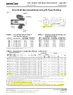


Introduction
The following instructions apply to the installation of electric
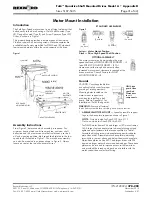
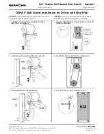
fans. Refer to Figure 1 for fan mounting location.
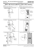
Assembly Instructions
WARNING: Consult applicable local and national safety codes
for proper guarding of rotating members.
Lock out power source and remove all external loads from drive
before servicing drive or accessories.
1. Remove V-belt guard assembly.
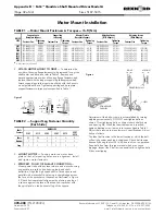
2. Insert four 1.25” (32 mm) long cap screws through fan
mounting holes in shroud with threaded portion of cap
screw away from drive. Secure cap screws to shroud with
flat washers and hex nut, see Figure 2.
3. Mount shroud to drive using spacers and hardware, see
Figure 1.
4. Assemble V-belt guard bracket.
5. Position the electric fan panel on the remaining threaded
portion of the cap screws and secure it to the shroud with
four locknuts, see Figure 2.
6. Remove the condensation plug from bottom of the fan.
7. Finish installing V-belt guard assembly per installation
instruction in Appendix L.
8. Connect electric fan to power source per local and
national electrical codes.
Rexnord Industries, LLC
378-200
(PN-2128394)
3001 W. Canal St., Milwaukee, WI 53208-4200 USA Telephone: 414-342-3131
November 2010
Fax: 414-937-4359 e-mail: [email protected] web: www.rexnord.com
Supersedes 6-07
Electric Fan Installation
MOTOR MOUNT
(SHOWN FOR REFERENCE)
SPACER
1.45" LONG (4307)
0.62" LONG (4315)
CAP SCREW
.625" x 2.50" (4307)
.625" x 1.50" (4315)
LOCK WASHER
SHROUD
ELECTRIC FAN
V-BELT GUARD BRACKET
(SHOWN FOR REFERENCE)
CAP SCREW
.625" x 1.25"
LOCK WASHER
SPACER
.32" LONG
Figure 1
SHROUD
CAP SCREW
.25" x 1.25"
HEX NUT
LOCKNUT
ELECTRIC FAN PANEL
(2) FLAT WASHERS
Figure 2
Appendix M
•
Falk™ Quadrive Shaft Mounted Drives Model A
(Page 44 of 44)
Sizes 5107-5315


