


TA Removal Tool
Introduction
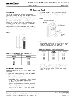
The patented TA removal tool offers a positive method for
removing a TA Taper equipped Quadrive from the driven shaft.
This method uses the torque multiplying characteristic of the
drive to separate the drive from the bushing and driven shaft.
The removal tool is available in kit form suitable for use with
Sizes 5107 thru 5315. The kit can be ordered from your
Rexnord-Falk Distributor by specifying “TA Removal Kit - Part
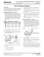
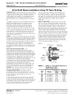
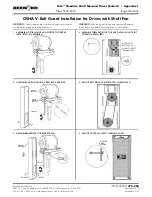
0769406". NOTE: Use of this tool requires a minimum axial
clearance ”M" shown in Figure 1 and Table 1.
CAUTION:
DO NOT modify the tool in any way OR use it in
another manner except to loosen the bushing nut as instructed
herein.
Preparation For Removal
WARNING:
Always “lock out” prime mover before working on
the Quadrive.
1. Quadrive shafts, input and output, must be free to rotate.
a) Remove any external load on the driven shaft.
b) Remove belts from input shaft sheave.
c) Remove the backstop (if so equipped). Refer to Section
II
— Step 10, for backstop removal instructions.
CAUTION:
DO NOT disconnect the drive from its torque
arm until the removal process is completed. In addition,
the drive must be supported during removal process. Use
a sling around the motor mount or as recommended in
SECTION
I
, Step 7. Be sure to take up the slack in the
sling before proceeding.
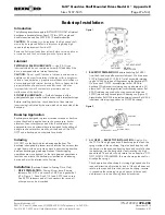
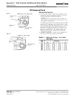
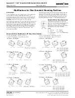
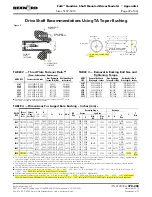
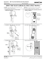
2. Loosen the setscrew on the O.D. of the bushing nut and
select the most convenient of the tapped holes in the
housing face for the threaded adapter. Figure 2.
3. Select the proper adapter from the tool kit. (Adapters are
marked with the Quadrive Size and part number.) Make sure
the tapped hole in the housing face is clean before inserting
the adapter. Apply tightening torque from Table 2.
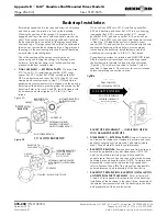
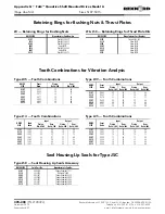
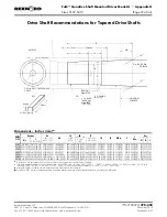
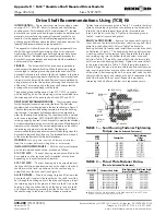
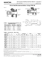
4. Mount the removal tool as illustrated in Figure 3 or 4. It is
generally preferable to install the tool in a position where
its weight will tend to keep it engaged into the nut. Then
rotate the input shaft until the tool hook engages one of
the slots in the nut.
Rexnord Industries, LLC
(PN-2128394)
378-200
3001 W. Canal St.,Milwaukee, WI 53208-4200 USA Telephone: 414-342-3131
November 2010
Fax: 414-937-4359 e-mail: [email protected] web: www.rexnord.com
Supersedes 6-07
M
Figure 1
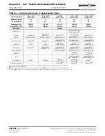
TABLE 1 — Minimum Tool Clearance –
Inches (mm)
DRIVE SIZE
M Dimension
5107
2.62 (67)
5115
2.62 (67)
5203
2.62 (67)
5207
2.62 (67)
5215
3.18 (81)
5307
3.18 (81)
5315
3.18 (81)
THREADED
ADAPTER
REMOVAL
TOOL
(3) TOOL
ADAPTER HOLES
DO NOT USE THIS HOLE
FOR SIZES 5107 & 5115
SETSCREW
Figure 2
TABLE 2 — Adapter Tightening Torque
DRIVE SIZE
Adapter
Part Number
Torque lb-ft (Nm)
5107
2111955
35 (47)
5115
2111956
70 (95)
5203
9111957
108 (146)
5207
2111958
120 (163)
5215
2111959
180 (244)
5307
2111959
180 (244)
5315
2111959
180 (244)
Falk™ Quadrive Shaft Mounted Drives Model A
•
Appendix C
Sizes 5107-5315
(Page 29 of 44)


