Getting r eady
Caster
Handle
Handle
Rear handle
Fig. 2
Fig. 3
Frame lock knob
Turn
clockwise or
counterclockwise
Fig. 4
ە
Frame lock status
Frame lock knob
Collar
Check to make sure knob is tightly
against collar with no gaps
Fig. 5
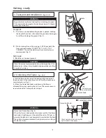
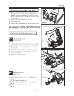
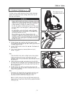
1. Transport and Installation
(Figs. 2 & 3)
Be particularly careful not to drop the unit during transport.
This may result in damage to the machine or injury if it should
land on your foot, etc.
WARNING
Transport
(1) The frame is locked before the product is packed. Hold up
the handle. The casters will contact the ground, allowing you
to roll the unit along the ground. (Fig. 2)
(2) When moving the unit by carrying it, lift it from both the
front and rear handles. DO NOT TR Y T O LIFT IT BY
YOURSELF. The unit should always be carried by two or
more people. (Fig. 3)
Setting up
(1) Place the unit on level ground.
Place the unit on level ground and in a stable position. If it is
placed on an incline, it may topple during operation, resulting
in accident or injury.
CAUTION
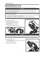
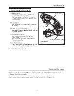
(1) Pull the frame lock knob on the bottom left hand side of
the motor and, at the same time, turn it 90¡ either clockwise or
counterclockwise. (Fig. 4)
(2) When the frame lock knob is protruding, the frame is
unlocked. When transporting the unit, use the same process in
reverse to lock the frame prior to transport.
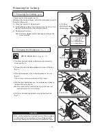
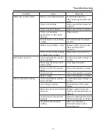
Frame Lock Precautions (Fig. 5)
When the frame is locked, check to make sure that the frame
lock knob is tightly against the end of the collar . If there is a
gap and the lock pin is not completely inserted into the hole,
the unit may become unlocked during transport, resulting in
accident or injury.
WARNING
2. Unlocking the Frame
(Figs. 4 & 5)
- 6 -
90
r
Summary of Contents for MANTIS 120A
Page 23: ...XB125 120 E4 0802R0200 S S ...


