(1)
(2)
(3)
(4)
(5)
(6)
Be sure to inspect the unit with the frame cover attached. If the
blade should come loose during inspection, it may fly out and
strike you in the face or otherwise lead to accident or injury.
WARNING
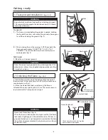
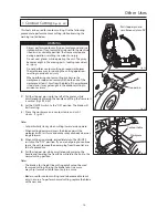
Attaching the blade
(Fig. 11)
・
A ttach the blade, using steps (1) through (5) in F ig. 10.
T hen turn the tension lever clockwise (6) to apply tension
to the blade.
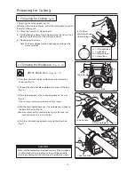
Fig. 13
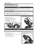
Fig. 12
Fig. 11
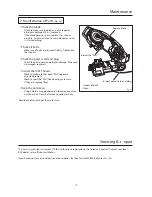
Checking the blade attachment
(Fig. 12)
・
Check to make sure the blade is properly attached.
・
Make sure the "SELI" bearings are inserted all the way.
・
Make sure the blade has not climbed up on the pulley
flange.
・
By hand, turn pulley A (on the wheel side) slowly anti-
clockwise and check to make sure the blade does not become
misaligned or come loose.
・
When blade attachment is complete, be sure to replace the
frame cover.
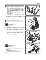
(1) Insert the power plug into the outlet.
(2) With the frame open, set the ON/OFF switch on the right front
section of the base to the "ON" position.
(3) Check the following:
・
Make sure there is no abnormal noise coming from the
motor or moving parts.
・
Make sure the blade does not become misaligned or come
loose.
・
Lower the frame and make sure the switch moves to the
"OFF" position.
(4) When all of the above have been checked, remove the plug
from the outlet.
5. Preliminary Inspection
(Fig. 13)
Getting r eady
Make sure blade
does not run up on
pulley flange
Make sure blade is
inserted all the way to
the rear of the "SELI"
bearings
Turn the pulley by hand
and make sure the blade
is stable
(1) Connect to
power outlet
(2) Switch ON
- 9 -
Summary of Contents for MANTIS 120A
Page 23: ...XB125 120 E4 0802R0200 S S ...


