4 Room Layout Overview for Installation
Page 6
Resonance Technology, Inc. CinemaVision System Installation / Operation Manual: RTC-CVSS Rev
12
4.
Room Layout Overview for Installation
WARNING: Absolutely no ferromagnetic tools should be brought inside the MRI Suite!
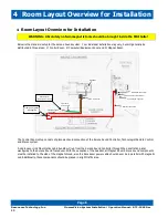
Below is the standard setup for the Serene Sound system. Your individual installation may vary, but will generally be
distributed in three areas: 1) Control Room, 2) Computer/Equipment Room and 3) Magnet Room.
The Control Room setup consists of placement and connection of the Serene Sound Controller, Technologist Remote Control
and Stereo system.
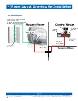
A single Laser Link Fiber Optics cable bundle will run from the Serene Sound Controller through the penetration panel
waveguide to the Serene Sound Transducer. With the exception of the headset, all Magnet Room Serene Sound components
must be installed to the side of the magnet shroud, also the transducer power cable should never be in parallel with magnetic
coil. Additionally, these components should be placed in a light traffic area.
Serene Sound Controller
Headset
Filter panel plate/
waveguide
Control Room Speakers
Transducer
power cable
Tablet/Remote Control
Transducer
MR Laser link Cable
MR Transducer
(white) power supply
Transducer power
Supply Cable
Summary of Contents for Serene Sound
Page 4: ......


