background image

© RESOL 11089 deltasol_c2.monen.ind

d

|

D e lt a S o l

®


C2

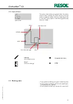
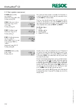
The system screen (active arrangement) shows the scheme 
which has been selected. The screen consists of several 
system component symbols, which are - depending on the 
current status of the system - either flashing, permanently 
shown or „hidden“.

sensor

collector 

pump

sensor

store

store heat exchanger

store top sensor

collector  

with collector sensor

pump

store

 1

with heat exchanger

temperature sensor

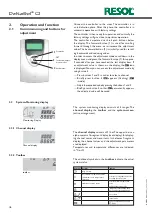
2.2.3  System-Screen

system screen

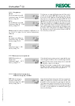
2.3   Flashing codes

  Pump symbols are flashing during the initialisation phase

  Sensor symbols are flashing when the corresponding sen-

sor display channel is selected.

  Sensor symbols are flashing in the case of a sensor fault.

Summary of Contents for DeltaSol C2

Page 1: ...l de Thank you for buying this RESOL product Please read this manual carefully to get the best performance from this unit RESOL D e lt a S o l C2 Mounting Connection Operation Troubleshooting Examples Manual 48002921 48002921 en ...

Page 2: ...the CE mark The Declaration of Conformity is available upon request please contact RESOL Note Notes are indicated with an information symbol Disposal Dispose of the packaging in an environmentally sound manner Dispose of old appliances in an environmentally sound manner Upon request we will take back your old appliances bought from us and guarantee an environmentally sound disposal of the devices ...

Page 3: ...egment display 7 segment display pictograms Operation 3 push buttons at the front of the housing Functions Temperature differential controller with optional add on func tions function control according to BAW guidelines operating hours coun ter tube collector function speed con trol and heat quantity measurement Inputs for 4 temperature sensors Pt1000 Output 1 semiconductor relay Bus RESOLVBus Pow...

Page 4: ...g of sensor cables and mains cables 1 Unscrew the cross head screw from the cover and re move it along with the cover from the housing 2 Mark the upper fastening point on the wall and drill and fasten the enclosed wall plug and screw leaving the head protruding 3 Hang the housing from the upper fastening point and mark the lower fastening point through the hole in the terminal box centres 130 mm D...

Page 5: ...1 5 6 Sensor 3 temperature sensor S3 7 8 sensor 4 e g sensor store TRF The mains connection is at the terminals 19 neutral conductor N 20 conductor L 12 ground clamp The controller is equipped with the RESOL VBus for data transfer with and energy supply to external modules The connection is carried out at the two terminals 9 and 10 marked VBus either polarity One or more RESOL VBus modules can be ...

Page 6: ...nd 2 in order to select a channel Briefly press button 3 appears flashing mode Adjust the requested value by pressing the buttons 1 and 2 Briefly press button 3 so that permanently appears the adjusted value will be saved forwards The system monitoring display consists of 3 ranges The channel display the toolbar and the system screen active arrangement The channel display consists of 2 lines The u...

Page 7: ...er flashing permanently shown or hidden sensor collector pump sensor store store heat exchanger store top sensor collector with collector sensor pump store 1 with heat exchanger temperature sensor 2 2 3 System Screen system screen 2 3 Flashing codes Pump symbols are flashing during the initialisation phase Sensor symbols are flashing when the corresponding sen sor display channel is selected Senso...

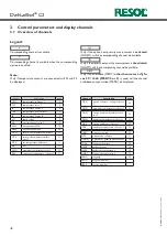
Page 8: ...perature store 1 9 S3 temperature Sensor 3 9 TRF temperature return sensor 9 S4 temperature Sensor 4 9 n speed relay 1 9 h P operating hours relay 1 9 kWh heat quantity kWh 10 MWh heat quantity MWh 10 DT O switch on temperature difference 11 DT F switch off temperature differ ence 1 11 DT S set temperature difference 11 RIS rise 11 S MX maximum temperature store 1 11 EM emergency temperature colle...

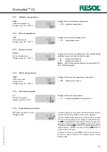
Page 9: ...t the sensor TRF temperature return TRF Other measured temperatures Display range 40 250 C 3 1 6 Operating hours counter The operating hours counter accumulates the solar operat ing hours of the relay h P Full hours are displayed The accumulated operating hours can be set back to zero As soon as one operating hours channel is selected the sym bol is displayed Press the SET 3 button for approx 2 se...

Page 10: ...e Adjustment range 0 3 Factory setting 1 MED Antifreeze concen tration in Vol When MEDT 0 or 3 is used the parameter MED is hidden Adjustment range 20 70 Factory setting 45 The flow rate as well as the reference sensors S1 flow and S4 return are used for calculating the heat quantity sup plied It is shown in kWh in the channel kWh uand in MWh in the channel MWh The overall heat quantity results fr...

Page 11: ... the controller can be adapted via the parameter Rise If the temperature difference falls below the adjusted switch off temperature difference DT F the controller switches off 3 1 10 Collector limit temperature Collector emergency shutdown If the adjusted collector emergency shutdown temperature EM is exceeded the controller will switch off the solar pump R1 in order to protect the system against ...

Page 12: ...erature Adjustment range 100 190 C Factory setting 120 C 3 1 11System cooling When the adjusted maximum store temperature is reached the system stagnates If the collector temperature increases to the adjusted maximum collector temperature CMX the solar pump is activated until the collector temperature falls below the maximum collector temperature The store temperature may increase subordinate acti...

Page 13: ...ue for the tube collector function will be recalculated OTC Tube collector function Adjustment range OFF ON Factory setting OFF For control and service work the operating mode of the controller can be manually adjusted For this purpose select the adjustment value HND1 The following adjustments can be carried out 3 1 17 Operating mode OFF relay off flashing AUTO relay in automatic operation ON rela...

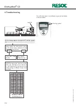
Page 14: ... on the display of the controller Warning symbol On the display appears the symbol and the symbol Sensor defect An error code is shown on the relevant sensor indication channel instead of a temperature 88 8 888 8 Line break Check the line Short circuit Check the line Pt1000 temperature sen sors pinched off can be checked with an ohmmeter In the following the resistance values corresponding to diff...

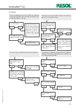
Page 15: ...Control replace Decalification no Heat exchanger plugged yes no Cleaning Heat exchanger too small yes Replace with correctly sized one no Plausibility control of the option tube collector spe cial function Change Ton and Toff accordingly Switch on temperature difference Ton too large no yes Collector sensor un favour able placed e g contact sensor instead of immersion sleeve sensor o k no Pump is ...

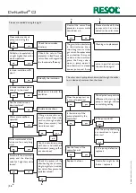
Page 16: ...than the store Does the pump start up in manual operation yes The adjusted tempe rature difference for starting the pump is too high choose an matching setting no Is the current of the pump released by the controller yes Is the pump stuck Turn the pump shaft using a screwdriver is it passa ble now Is the pump defective replace it Are the fuses of the controller o k Controller might be de fective r...

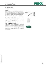
Page 17: ...rs flatscrew sensors outdoor temperature sensors indoor temperature sensors cylindrical clip on sensors also as complete sensors with immersion sleeve For more information see our catalogue and price list VBus USB interface adapter The new VBus USB interface adapter is the interface between the controller and a personal computer With its standard mini USB port it enables a fast transmission of sys...

Page 18: ... RESOL 11089 deltasol_c2 monen indd 18 D e lt a S o l C2 Notes ...

Page 19: ... RESOL 11089 deltasol_c2 monen indd 19 D e lt a S o l C2 Notes ...

Page 20: ...Regelungen GmbH This especially applies for copies translations micro films and the storage into electronic systems Editor RESOL Elektronische Regelungen GmbH Important notice We took a lot of care with the texts and drawings of this manual and to the best of our knowledge and consent As faults can never be excluded please note Your own calcu lations and plans under consideration of the current st...

Reviews: