APPENDIX B
–
Advanced Gate Controller Configurations
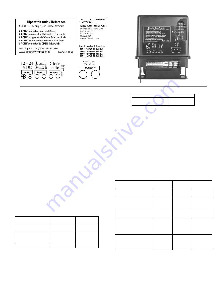
From left to right, Gate Controller Terminals are:
−
−
−
−
−
−
−
−
Optional power input. +9Vto +24VDC. Make sure that
your gate’s DC power supply “Ground” is wired to
terminal 2.
Ground or Common terminal.
Limit switch input A. Wire such that when the limit
switch is closed, terminal 4 is shorted to terminal 3.
Limit switch input B. Wire such that when the limit
switch is closed, terminal 4 is shorted to terminal 3.
Secondary Relay Contact A. Up to 120VAC LOW
CURRENT contact. Max ½ amp. Typically wired to
optional “Close Gate” input on Automatic Gate Opener.
Secondary Relay Contact B. Up to 120VAC LOW
CURRENT contact. Max ½ amp. Typically wired to
optional “Close Gate” input on Automatic Gate Opener.
Primary Relay Contact A. Up to 120VAC. Max 10 amps.
Typically wired to “Open Gate”, “Open/Close” or
“Remote” input on Automatic Gate Opener.
Primary Relay Contact B. Up to 120VAC. Max 10 amps.
Typically wired to “Open Gate”, “Open/Close” or
“Remote” input on Automatic Gate Opener.
Selecting Gate Controller “ON” Time
For most connections to an Automatic Gate Opener, the
default setting of ½ second is best. However, for
connection to yard lights, cameras, etc., you may wish
to adjust how long the connected device stays on.
Gate Controller
“ON” Time
Dipswitch
#3
Dipswitch
#4
½ second –
No Limit Switch
OFF OFF
½ second –
Using a Limit Switch
ON OFF
10 seconds
OFF
ON
30 seconds
ON
ON
NOTE:
For most gate system wiring,
dipswitch #4 should be left “OFF.” If
you wire your gate controller to a
limit switch, dipswitch #3 should be
turned “ON”.
Enabling the Auto-Close Feature
Auto-Close Feature
Dipswitch #6
OFF (disabled)
OFF
ON (enabled)
ON
By enabling the Auto-Close feature, the Gate Controller
will attempt to close the gate 45 seconds after it is
opened. This feature will work better if your
configuration has at least one of the following elements:
Separate Open / Close Terminals,
A “Gate Closed” Sensor or limit switch, or
A “Gate Open” Sensor or limit switch
Otherwise, the Gate Controller must assume that the
gate has not opened or closed for any other device.
Warning:
Please remember safety! Do not enable
auto-close where it might pose a risk
of entrapment, causing injury, death,
or damage to vehicles
.
Using Additional Contact / Clearance Sensors
NOTE:
To power an additional contact sensor that is
NOT already connected to your gate system,
short terminal #3 to ground, connects the
switch across terminals 3 and 4, and turn
dipswitch #8 ON.
Open/Closed Contact
Sensors
Dipswitch
#3
Dipswitch
#7
Dipswitch
#8
No contact sensors
used
OFF OFF OFF
“Closed” limit switch
wired to terminals #3
and #4
ON
OFF
OFF
“Open” limit switch
wired to terminals #3
and #4
ON
ON
OFF
Additional “Closed”
limit switch or sensor
wired to terminals #3
and #4
ON
OFF
ON
Additional “Open”
limit switch or sensor
wired to terminals #3
and #4
ON
ON
ON
6


