background image


impedance  of  measured  circuit  was  smaller  than  10MΩ,  the  measurement  error 
would be so tiny that could be neglected (0.1% or even smaller). 


AC voltage measurement 


1.  Connect the red test lead to the 

“VΩmA” 

jack and the black test lead to the 

“COM” 

jack. 

2.  Set the range switch to the desired AC voltage range (V~). 
3.  Connect the test leads across the device or circuit to be measured. Read the 

voltage value on the LCD display along with the polarity. 


The measurement diagram and 

WARNING 

information are both the same as DC voltage 

measurement. 


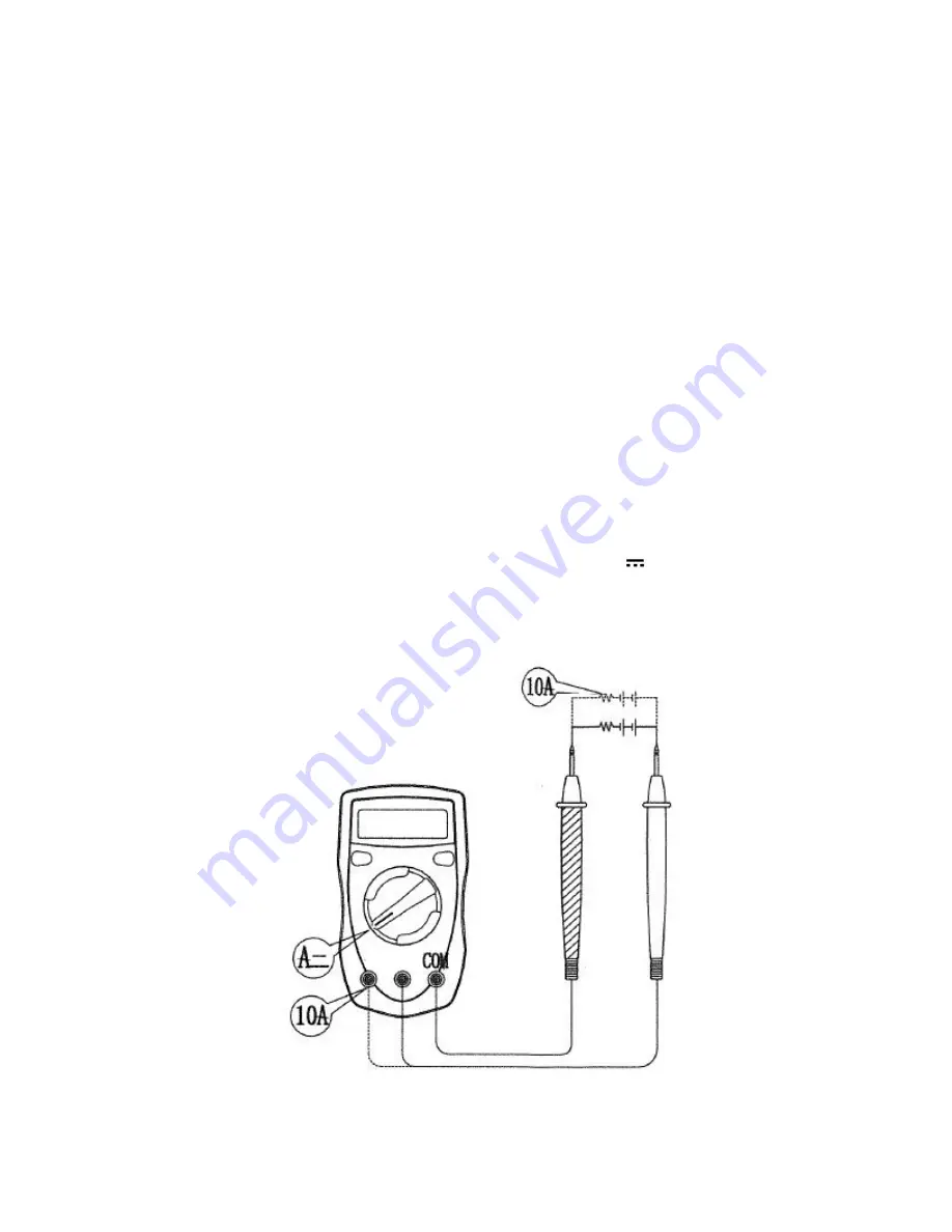
DC current measurement 


1.  Connect the red test lead to the 

“VΩmA” 

jack or 

“10A” 

jack, and the black test 

lead to the 

“COM” 

jack. 

2.  Set the range switch to the desired DC current range (A

). 

3.  Open the circuit in which the current is to be measured, and connect the test 

leads in series with the circuit. 

4.  Read the current value on the LCD display along with the polarity. 


Measure current 

Summary of Contents for RNG-TOOL-MM

Page 1: ...0 RENOGY Multimeter RNG TOOL MM Palm Size Digital Multimeter 2775 E Philadelphia St Ontario CA 91761 1 800 330 8678 Version 1 0...

Page 2: ...using the meter Use the meter only as specified in this manual or the protection provided by the meter might be impaired or lost Inspect the meter before using it Do NOT use the meter if it appears da...

Page 3: ...e connections It will damage the meter and pose hazard When there is a 1 symbol on the LCD display replace the battery in time to keep the measurements accurate Do NOT use the meter under high tempera...

Page 4: ...Operation 6 DC voltage measurement 6 AC voltage measurement 7 DC current measurement 7 Resistance measurement 8 Diode measurement 9 Battery measurement 10 Technical Specifications 10 DC voltage 10 AC...

Page 5: ...C Important Safety Info Diode General Specifications Maximum input voltage between terminals and earth ground 500Vrms 10A JACK No fuse Fuse for mA JACK 5x20 F 315mA 250v Range selection Manually Backl...

Page 6: ...nd range switch select the functions and desired ranges as well as to turn ON OFF the meter 5 COM JACK return terminal for all measurements plug in connector for black negative test lead 6 10A JACK In...

Page 7: ...ct the test leads across the device or circuit to be measured Read the voltage value on the LCD display along with the polarity Measure voltage WARNING Do NOT test more than 500V voltage which might d...

Page 8: ...cuit to be measured Read the voltage value on the LCD display along with the polarity The measurement diagram and WARNING information are both the same as DC voltage measurement DC current measurement...

Page 9: ...efore measurements you should firstly set the meter at the highest range and then gradually lower the range according to the reading For the mA input jack overload will open the built in fuse You must...

Page 10: ...ng This is a normal phenomenon Diode measurement 1 Connect the red test lead to the V mA jack and the black test lead to the COM jack 2 Set the range switch to the desired diode range 3 Connect the re...

Page 11: ...voltage CAUTION Do NOT input more than 60VDC or 30VAC voltage It might damage the meter and harm your safety Technical Specifications Accuracy specifications of reading number of least significant dig...

Page 12: ...10A 10mA 2 5 NOTE Overload protection F 315mA 250v fused 10A range unfused To use safely each measurement cannot last for more than 10 seconds and the interval between each measurement must be more t...

Page 13: ...ry should be replaced Please follow the instructions below 1 Set the range switch at OFF position to turn the meter off 2 Disconnect the test leads from the measured circuit and remove the test leads...

Page 14: ...eads were disconnected from the measured circuit before opening the back case 2 Only use damp cloth and a little gentle detergent to clean the meter NEVER use chemical solvent Renogy reserves the righ...

Reviews: