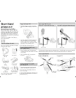
background image

13

MP18-S

dimensions mm (in)

17.5°                        17.5°

21,5

(0.85)

Ø62

(Ø2.24)

Stylus
length

Ø48 (Ø1.89)

95

(3.74)

29

(1.14)

22

(0.87)

85

(3.35)

A

Ø6 (Ø0.24)


B

Ø14,25

(Ø0.56)

7,13

(0.28)

4 (0.16)

Drive slot

90°

To save battery life, the shank switch
must NOT be depressed, during
the time the probe is held in the tool
store.
It may be nesessary to provide a
storage location with a clearance
around the switch.

Thread for pull stud

TAPER SHANK
Complete probe/shank units are
supplied by Renishaw. These
shanks incorporate a switch.

The shank is attached to the

RMP3 using a shank adaptor.
Part No. A-2249-0134.

The method of attachment is
shown on page 15.

BT

40

35

(1.38)

14

(0.55)

BT

50

50

(1.97)

24

(0.94)

ANSI B5.50 - 1985 (CAT)

40

35

(1.38)

14

(0.55)

ANSI B5.50 -1985 (CAT)

50

65

(2.56)

36,8 (1.45)

DIN 69871

40

50,6 (1.99)

14

(0.55)

DIN 69871

50

50,6 (1.99)

36,8 (1.45)

ANSI (CAT) MODIFIED

40

35

(1.38)

14

(0.55)

ANSI (CAT) MODIFIED

50

65

(2.56)

36,8 (1.45)

Dimensions

ISO

taper

A

       B

Shank type

SHANKS AVAILABLE

These shank specifications are for certain Cincinatti Milacron machines.
Generally to ANSI B5.50 - 1985 (CAT), but with a metric thread for the pull stud.

Orders placed for MP18-S probes require a separate quotation and price.
Please contact Renishaw Custom Products Department.

Taper

shank

RMP3

Shank switch

Summary of Contents for MP18

Page 1: ...MP18 433 MHz LP USA MP18 Probe System selectable channel radio transmission Installation and User s Guide ...

Page 2: ...Transmission are the subject of the patents and patent applications listed below EP 108521 JP 326 001 1992 US 4 599 524 EP 501680 JP 89 397 1993 US 4 636 960 EP 506318 JP 1 847 335 US 4 636 960 EP 652413 JP 1 942 442 US 5 272 817 FCC DECLARATION USA FCC ID KQG RMP3 433 ...

Page 3: ...e radio frequency energy and This product has been tested to the following European Standards I ETS 300 220 October 1993 ETS 300 683 June 1997 if not installed and used in accordance with the instruction manual may cause harmful interference to radio communications Operation of this equipment in a residential area is likely to cause harmful interference in which case you will be required to correc...

Page 4: ...erieklemmen nicht in Kontakt mit metallischen Gegenständen bringen Anleitungen über die sichere Reinigung von Renishaw Produkten sind in Kapitel MAINTENANCE WARTUNG in der Produktdokumentation enthalten Bevor Wartungsarbeiten begonnen werden muß erst die Stromversorgung getrennt werden Beziehen Sie sich auf die Wartungsanleitungen des Lieferanten Die Einheit muß von einer Schutzkleinspannungsverso...

Page 5: ...er les batteries Utiliser uniquement les batteries recommandées Veiller à ce que les bornes de la batterie n entrent pas en contact avec d autres objets métalliques Les conseils de nettoyage en toute sécurité des produits Renishaw figurent dans la section MAINTENANCE de votre documentation Mettre la machine hors tension avant d entreprendre toute opération de maintenance Consulter le mode d emploi...

Page 6: ...rata Extra conforme agli essenziali requisiti della NS EN 61010 o analoghe specifiche NL VEILIGHEID Oppassen voor onverwachte beweging De gebruiker dient buiten het werkende signaalveld van de sondekop extensie sonde combinaties te blijven De batterijen volgens de aanwijzingen van de fabrikant hanteren en wegdoen Gebruik uitsluitend de aanbevolen batterijen Zorg ervoor dat de poolklemmen niet in c...

Page 7: ... Separated Extra Low Voltage baixa voltagem extra separada de 24 V c d em conformidade com os requisitos essenciais da norma BS EN 61010 ou de outra especificação semelhante SW SÅKERHET Se upp för plötsliga rörelser Användaren bör befinna sig utanför arbetsområdet för sondhuvudet förlängningen sond kombinationerna Hantera och avyttra batterier i enlighet med tillverkarens rekommendationer Använd e...

Page 8: ... MI16 audio diagnostics 20 MI16 output waveforms 20 MI16 panel mounting kit 20 PSU3 POWER SUPPLY UNIT 21 OM16 OPTICAL MODULE 22 MI18 BATTERY POWER 24 MODES OF OPERATION 25 MODE AND CHANNEL SELECTION 26 PROGRAMMING THE MI16 INTERFACE 26 RADIO FREQUENCY AND CHANNEL SEPERATION 27 PROGRAMMING THE PROBE RMP3 MODULE 28 MAINTENANCE Stylus spring pressure adjustment 29 Diaphragm inspection and replacement...

Page 9: ...module probe RMP3 transmits a probe signal to the two radio modules machine RMM2 using frequency modulated FM radio waves The signal then passes via cable to the MI16 interface and onto the CNC machine control thereby recording the stylus contact position in the machine tool registers Two different contact positions enable features to be measured Probing software is available from Renishaw FEATURE...

Page 10: ...obe to shank adaptor plate Part No A 2249 0134 Radio Module Machine transmits and receives signals between machine control and Radio Module Probe RMP3 Signals received by the RMM2 pass via coaxial cable to the MI16 machine interface which decodes and converts them into solid state relay SSR outputs for use by the machine tool s CNC controller An M code causes the OM16 optical transmission module t...

Page 11: ...28oz PROBE SEALING IPX8 BS 5490 IEC 529 100kPa 1 atmosphere SYSTEM DELAYS The time delay from the probe stylus contacting the workpiece and the MI16 machine interface providing an output signal to the CNC controller is 12ms 10µs STYLUS OVERTRAVEL LIMITS 21 5mm 0 85in Z X Y 17 5 17 5 Stylus length 50mm 1 96in 100mm 3 93in X Y 21 5mm 0 84in 36 5mm 1 43in Z 8mm 0 31in 8mm 0 31in TEMPERATURE PROBE RMP...

Page 12: ...5 2 0 598 15 2 0 598 M 2045 0064 30 35 25 1 388 19 0 19 1 0 748 0 752 M 2045 0065 40 35 25 1 388 19 0 19 1 0 748 0 752 M 2045 0066 45 35 25 1 388 19 0 19 1 0 748 0 752 M 2045 0067 50 35 25 1 388 19 0 19 1 0 748 0 752 M 2045 0137 40 35 25 1 388 19 0 19 1 0 748 0 752 M 2045 0138 45 35 25 1 388 19 0 19 1 0 748 0 752 M 2045 0139 50 35 25 1 388 19 0 19 1 0 748 0 752 M 2045 0077 30 27 5 1 083 27 5 1 083...

Page 13: ...e RMP3 using a shank adaptor Part No A 2249 0134 The method of attachment is shown on page 15 BT 40 35 1 38 14 0 55 BT 50 50 1 97 24 0 94 ANSI B5 50 1985 CAT 40 35 1 38 14 0 55 ANSI B5 50 1985 CAT 50 65 2 56 36 8 1 45 DIN 69871 40 50 6 1 99 14 0 55 DIN 69871 50 50 6 1 99 36 8 1 45 ANSI CAT MODIFIED 40 35 1 38 14 0 55 ANSI CAT MODIFIED 50 65 2 56 36 8 1 45 Dimensions ISO taper A B Shank type SHANKS...

Page 14: ...ws C to 2 3 Nm 1 47 2 2 lbf ft 6 Mount the probe shank assembly into machine spindle 2 5mm AF 4mm AF STYLUS ON CENTRE ADJUSTMENT 7 Each of the four screws B will move the probe relative to the shank in the X or Y direction as pressure is applied Tighten individually backing off after each movement 8 When the stylus tip run out is less than 20µm fully tighten screws C to 6 8 Nm 4 4 5 9 lbf ft 9 For...

Page 15: ...dle and use one of the following procedures 1 Rotate stylus close to a reference surface check if the gap is constant 2 Rotate stylus against low force dial test indicator which does not unseat the probe 3 Use method advised by machine tool supplier MP18 and MP18 S STYLUS ON CENTRE ADJUSTMENT STYLUS ON CENTRE ADJUSTMENT 1 If adjustment is required remove the battery covers and battery 2 Slacken th...

Page 16: ...perating on the same channel An audio monitoring facility is provided to diagnose causes of interference see page 18 RMM2 MOUNTING Select a flat metallic surface ideally away from corners and bulkheads The base of each RMM2 incorporates five permanent magnets to allow temporary attachment to a metal surface Alternatively three clearance holes are provided within the base for M4 fixing screws 10mm ...

Page 17: ...nect the second RMM2 cable to either of the MI16 antenna inputs Position the second RMM2 such that the regions of weak signal do not coincide with those observed with the first RMM2 A good solution is to mount antennae at 90 to each other 270mm 10 63in Rear view REAR EXIT CABLE Top view 60mm 2 36in 40mm 1 57in 270mm 10 63in Once a suitable position has been established reconnect the first RMM2 and...

Page 18: ...f MI16 INTERFACE dimensions mm in 7 PROBE STATUS LED Lit when the probe is seated Off when triggered 8 ERROR LED Lit when an error occurs in the transmission of the probe signal or when the probe is off 9 LOW BATTERY LED Lit when the battery voltage falls below 7V Replace the batteries as soon as possible after this LED lights up 10 AUDIO VOLUME CONTROL Adjusts the volume of the audible transmissi...

Page 19: ...MALLY OPEN 16 PROBE STATUS SSR NORMALLY OPEN 17 BNC CONNECTOR FOR FIRST ANTENNA 18 BNC CONNECTOR FOR SECOND ANTENNA 19 CHASSIS GROUND The MI16 is equipped with an internal power transformer which ensures that the casing is isolated from the external power source To maintain the isolation the positive and negative wires must be connected without contacting the chassis Use of a shielded cable is pre...

Page 20: ...tch on Error clear Closed Normally Open Closed Open Open Open Normally Open Closed Normally Closed PROBE STATUS ERROR LOW BATTERY Closed Normally Closed Solid State Relay Relay PROBE STATUS With the RMP3 inactive no tone should be audible only background noise In either condition the sound should be observed and any unusual sounds noted The frequency of occurrence may then be correlated to adjacen...

Page 21: ...d for use world wide INPUT Power to the PSU3 is provided via an IEC mains connector 85 264V ac 47 66Hz 25W maximum OUTPUT 24V 2V dc 0 5 A maximum The PSU3 is over voltage and over current protected Self adhesive foot Ø12 7mm 0 5in Green LED PSU3 POWER SUPPLY UNIT optional 140mm 5 5in 3 5mm 0 14in 44mm 1 73in 183mm 7 2in dimensions mm in ...

Page 22: ...ule The bracket securing screws can be loosened to allow the OM16 LED s to be directed towards the probe LED s Screws are then re tightened The mounting bracket accepts an M10 size bolt for attachment to guarding or bulkheads OM16 WINDOW The chosen position for the OM16 should be selected to avoid direct impact of machining swarf on the OM16 window Although the window is 4mm thick toughened glass ...

Page 23: ...d the screen These should be connected as below Cable screen Connect to ground MI16 pin 4 see page 19 Red and Yellow Connect both to the ve OM16 pin on the MI16 Interface MI16 pin 5 see page 19 Blue and Green Connect both to the ve OM16 pin on the MI16 Interface MI16 pin 6 see page 19 SEALING The OM16 is sealed to IP68 A gland suitable for sealing to flexible conduit is supplied as stan dard The O...

Page 24: ...proaching The Low Battery LED will only light up during the probe operating mode The machine control may also be programmed to flag up a Low Battery Alarm Typical battery reserve life Using an alkaline battery at 5 usage the probe will typically continue to operate for 8 hours after the MI 16 Low Battery LED lights up Dead battery indication When the battery voltage drops below the threshold where...

Page 25: ...tical on Time out off Spin on Spin off centrifugal switch Spin on Time out off SWITCH OFF METHOD A machine M code causes the OM16 to send an optical signal to the RMP3 which switches it off The RMP3 will switch off once the timeout period elapses since the last probe trigger or since the RMP3 was last switched on whichever was later The machine spindle is rotated at 500 rev min 50 rev min for a mi...

Page 26: ...ss will cause the activation method to change The MI16 can be cycled through all the available activation methods is carried out on the MI16 and transferred to the RMP3 by a short range optical link To program the RMP3 it is necessary to bring the RMP3 close to the front panel of the MI16 Interface This should be catered for when selecting the MI16 Interface mounting and positioning 4 When a Mk2 M...

Page 27: ...33 433 875 34 433 900 35 433 925 36 433 950 37 433 975 38 434 000 39 434 025 40 434 050 41 434 075 42 434 100 43 434 125 44 434 150 45 434 175 46 434 200 47 434 225 48 434 250 49 434 275 50 434 300 51 434 325 52 434 350 53 434 375 54 434 400 55 434 425 56 434 450 57 434 475 58 434 500 59 434 525 60 434 550 61 434 575 62 434 600 63 434 625 64 434 650 65 434 675 66 434 700 67 434 725 68 434 750 69 4...

Page 28: ...ry second for 5 seconds and the front panel displays the current RMP3 configuration 6 If the RMP3 is now moved away from the MI16 Interface no programming will take place Useful if the user wishes to verify the current configuration of the RMP3 7 If the RMP3 is held in position see action 4 a continuous audible beep will be emitted for 5 seconds to warn that programming is about to occur If the RM...

Page 29: ...acken the locknut and turn the adjusting screw anticlockwise to reduce pressure more sensitive or clockwise to increase pressure less sensitive A stop prevents damage which could be caused by overtightening the adjusting screw Finally tighten the locknut to 1Nm 0 74lbf ft and replace the probe head STYLUS SPRING PRESSURE ADJUSTMENT Gauging force Align contact pins before connecting probe head DO N...

Page 30: ...inner diaphragm If damaged return the probe to your supplier for repair OUTER DIAPHRAGM INSPECTION 1 Remove the stylus 2 Unscrew the front cover 3 Inspect outer diaphragm for damage 4 To remove outer diaphragm grip near the middle and pull upwards INNER DIAPHRAGM INSPECTION 5 Inspect inner diaphragm for damage If damaged return the probe to your supplier for repair DO NOT REMOVE INNER DIAPHRAGM OU...

Page 31: ...ting plate RMP3 Probe head 2 5mm AF 1 1 Nm 0 8 lbf ft 2 5mm AF 1 1 Nm 0 8 lbf ft 7mm AF 1 Nm 0 74 lbf ft 5mm AF 2 Nm 1 7 lbf ft 2 Nm 1 7 lbf ft Weak link optional for steel shaft styli only 2mm AF Align RMP3 and probe head electrical contacts 2mm AF 1 1 3 5 Nm 1 1 2 6 lbf ft 3mm AF 2 Nm 2 21 lbf ft 2 5mm AF 1 1 Nm 0 8 lbf ft 2 5mm AF 1 1 Nm 0 8 lbf ft ...

Page 32: ...MI16 RMM2 x two ANSI 1978 SIZE 45 shank adaptor shank tool kit MP18 S KIT MP18 S probe MI16 RMM2 x two ANSI 1978 SIZE 50 shank adaptor shank tool kit MP18 S KIT MP18 S probe MI16 RMM2 x two DIN 69871 SIZE 40 shank adaptor shank tool kit MP18 S KIT MP18 S probe MI16 RMM2 x two DIN 69871 SIZE 45 shank adaptor shank tool kit MP18 S KIT MP18 S probe MI16 RMM2 x two DIN 69871 SIZE 50 shank adaptor shan...

Page 33: ...nna rear exit cable MI16 A 2137 0160 MI16 interface with connector OM16 kit A 2137 0401 OM16 optical module and mounting bracket Battery P BT03 0001 Duracell MN1604 PP3 9V Stylus A 5000 3709 PS3 1C stylus Ø6 ball x 50mm long with ceramic stem Weak link kit A 2085 0068 Kit comprising stylus weak link stem x two spanner and instruction sheet Weak link stem M 2085 0069 Stylus weak link stem for use w...

Page 34: ...terface and the OM16 optical module Probe RMP2 RMP3 The RMP2 and RMP3 will communicate with the RMM and RMM2 provided they are set to operate on the same channel The MP18 probe is smaller and lighter than the MP14 and MP16 probes RMM and RMM2 antenna Both antenna use the same base The RMM2 antenna is shorter than the RMM antenna Interface unit The MI14 interface has been replaced by the MI16 inter...

Page 35: ... MP18 shank adaptor shank without shank switch GAUGE LINE A B 6 0 24 C Ø20 10 0 791 Ø20 02 0 788 Two holes M8 x 1 25 Thro equi spaced into bore For reference only 27 5 1 08 25 5 1 00 0 8 32 0 8 32 Not convex 4 5 0 18 4 3 0 17 Ø25 0 0 984 Ø24 8 0 976 0 05 C 0 02 Dimensions A and B are shown on page 12 ...

Page 36: ... LOW The reception sensitivity is lower ð The reception distance is smaller ð The parasitic sensitivity is diminished MEDIUM This position is a compromise between the two previous ADVICE ON SELECTION OF SWITCH POSITION The choice of the switch position is dependent on the probe power version sold in the different markets The following positions are recommended HIGH USA Market LOW CEE Market MEDIUM...

Page 37: ...aly renishaw com Renishaw KK Across City Nakano Sakaue 38 1 Chuo 1 chome Nakano ku Tokyo 164 0011 Japan Tel 81 3 5332 6021 Fax 81 3 5332 6025 email japan renishaw com Renishaw Iberica S A Edificio Océano Calle Garrotxa 10 12 Parque Más Blau 08820 Prat de LLobregat Barcelona Spain Tel 34 93 478 21 31 Fax 34 93 478 16 08 email spain renishaw com Renishaw A G Poststrasse 5 CH 8808 Pfäffikon Switzerla...

Reviews: