background image

SECTION 2 

INSTALLING PRINTER 


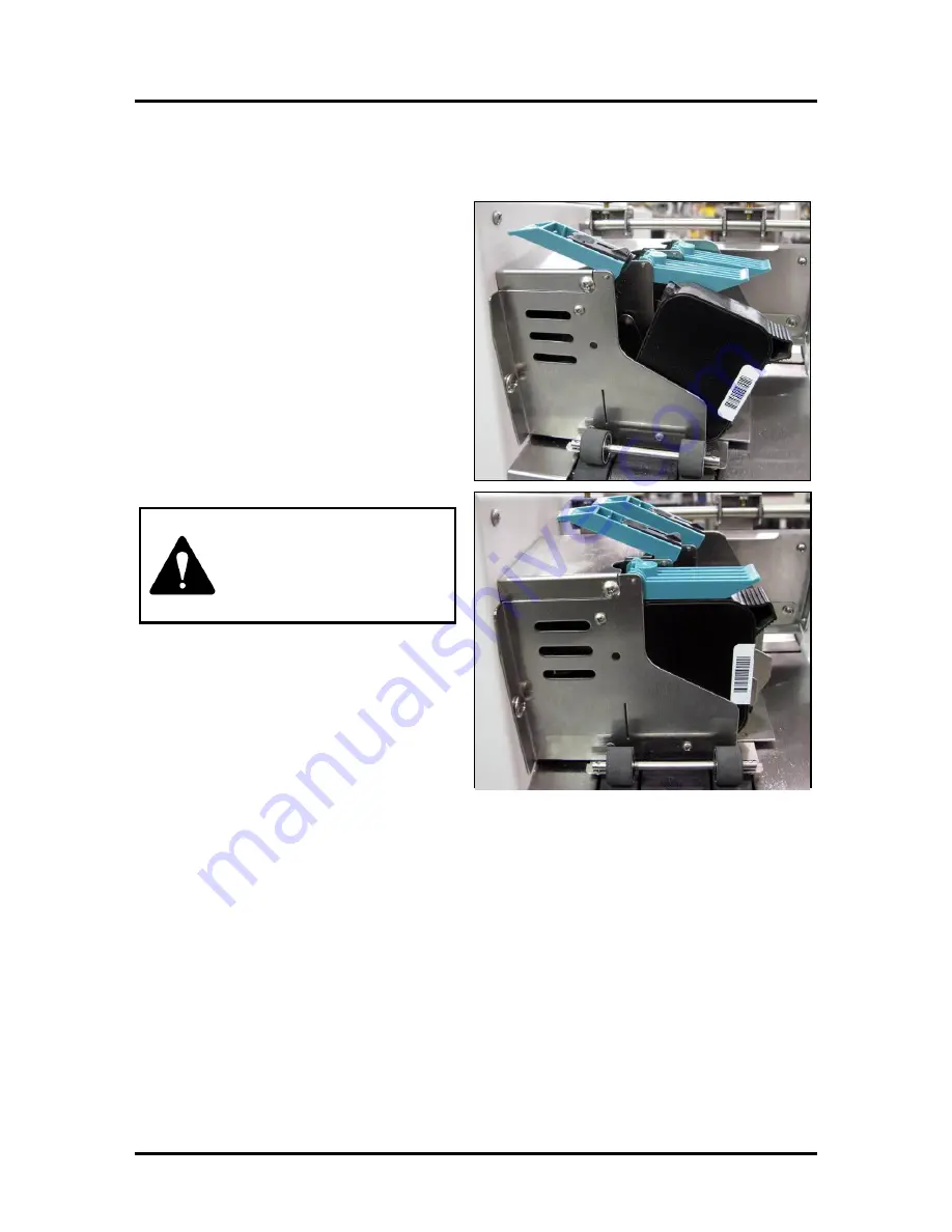
Install Inkjet Cartridges 

Printer has 3 Inkjet Cartridges. 

To install Cartridges:


1.


Remove Inkjet Cartridge from packaging. 
Take care not to touch copper contacts, 
metal plate, or gold printhead. Remove 
protective tape from Printhead. 

2.


Open Latch Lever mounted on Inkjet 
Cartridge Holder. 

3.


With Cartridge’s Printhead pointing 
down, slide Cartridge into Holder. Push 
down and toward contacts in Holder. 

4.


Make sure Cartridge is seated in Holder. 
Close Latch Lever to secure Cartridge. 

DO NOT

 force Latch Lever into place.  

5.


Repeat 

Steps 1-4

 for remaining  

Inkjet Cartridges. 


Ink in Cartridge may be 
harmful if swallowed.  
Keep new and used 
Cartridges out of reach of 
children. Discard empty 
Cartridges immediately. 


Summary of Contents for AS-150

Page 1: ...AS 150 PRINTER SERVICE MANUAL Rev 10 14 15...

Page 2: ...equipment Make sure there is no strain on power cord caused by jamming it between equipment walls or furniture DO NOT remove covers Covers enclose hazardous parts that should only be accessed by a qu...

Page 3: ...ontrol Panel 19 Purge While Printing 21 Printer Driver Properties 22 PC Board and Electrical Component Location 25 SECTION 4 Adjustments 26 Drive Belt Tension Adjustment 26 Encoder Belt Tension Adjust...

Page 4: ...Support Guide 6 Operator Manual Assembling Printer Tools required Standard 2 Phillips head screwdriver Install Side Guides 1 Remove two screws from Side Guide Blocks 2 Position Side Guide screw holes...

Page 5: ...Rear Media Support 1 Install Rear Media Support using two screws A included onto Rear Center Plate as shown Install Rear Media Guide 1 Insert Adjusting Knob A through Rear Media Guide and Rear Media S...

Page 6: ...115 220 Volt AC 50 60 Hz grounded outlet CAUTION DO NOT USE ADAPTER PLUGS OR EXTENSION CORDS TO CONNECT PRINTER TO WALL OUTLET DO NOT USE WITH OUTLETS CONTROLLED BY WALL SWITCHES DO NOT USE WITH OUTLE...

Page 7: ...en Latch Lever mounted on Inkjet Cartridge Holder 3 With Cartridge s Printhead pointing down slide Cartridge into Holder Push down and toward contacts in Holder 4 Make sure Cartridge is seated in Hold...

Page 8: ...ion on Table 4 Loosen Separator locking screw Place Separator on media and tighten locking screw Repeat for remaining Separator 5 Adjust Side Guides so they are about 1 32 from sides of media Tighten...

Page 9: ...r to view files Then select and double click Setup exe 3 Add Update or Delete Printer window opens Click Add New Printer Click Next 4 Install Printer Driver window opens Select manufacturer and model...

Page 10: ...mwareMgr exe to start the program 3 BIOS Manager window opens Click Browse to find the new firmware Select the new BIOS file from the list of BIOS Click on the selection 4 BIOS Manager window opens ag...

Page 11: ...Replace with fuse of same rating Bad Controller PC Board Replace Bad Power Supply Replace Interface Communication Problems CONDITION PROBLEM SOLUTION Printer does not respond to software Connection p...

Page 12: ...r PC Board Feeding Problems CONDITION PROBLEM SOLUTION Intermittent feeding Feed Ramp not used Side Guides set improperly Dirty Feed Rollers Paper stuck together Bad or dirty Sensor Uneven mail piece...

Page 13: ...kness Maximum thickness 0 020 Press ENTER key check for broken Drive Belt and replace check for loose set screws on Drive Pulley or Belt Drive Roller Pulley Replace Clutch Check or replace Motor See P...

Page 14: ...e Install new Ink Cartridge Check voltages Check Flex Circuit for tears Print slanted or skewed Skew within specs Side Guides not set properly 2 5 from bottom edge of material Readjust Side Guides Gra...

Page 15: ...locked the Ink Chamber Wiping wrong way or too hard drove particles into Nozzles Cartridge low on ink Tape covering Print Nozzle or Vent Holes Printhead connections not set Bad Printhead Drive Card Cl...

Page 16: ...eference point in center of scale to help you align print on media Address prints upside down on media Layout and or media direction incorrect Change direction from Normal to Inverted or Inverted to N...

Page 17: ...d If using a combined field barcode choose USPS barcode font Put zip code field in database or use another database Enable barcode Unwanted BOLD Italic or Underlined type Turned on in layout Open layo...

Page 18: ...there is a problem with Clutch circuitry Clutch Test 2 This test is designed to operate Clutch in an ON and OFF mode Selecting this test and pressing ENTER causes Clutch to actuate and de actuate in...

Page 19: ...Initiates Print function through File menu 6 Selects whether job has an Overlay or not through Printer Driver Properties menu 7 Clicks Print button to print job Printing Job 1 Once a job is sent to P...

Page 20: ...PC and gets ready for printing 3 This cycle repeats itself as long as there is media in Feeder 4 Either cycle stops when Feeder runs out of media operator stops the process or no records remain to be...

Page 21: ...features Features available Clear Batch Counter Pressing ENTER clears the number in upper right hand corner of display Resetting Counter is usually performed at the start of each job Turning Printer...

Page 22: ...Cartridge Repeat for each Cartridge you install When ENTER is pressed display changes to Head n has a new cartridge To check Cartridge ink levels press and hold TEST PRINT until Service Menu appears U...

Page 23: ...current job Press MENU then step to Press Enter to Purge Press ENTER to start purge and press ENTER again to stop purge Press ONLINE then ENTER to get back to normal printing NOTE If a paper jam occu...

Page 24: ...n Through Properties you can control the Printer s output Use the Properties windows to customize Printer s output To start printing click File then Print Print window opens To print the job click Pri...

Page 25: ...int Document Options Document Options is used to set halftoning options and enable Print Optimizations In Printer Features you can set the resolution of Printer set the language the printer operates i...

Page 26: ...d to put more space between pieces as they are printed This gives first piece printed more time to dry before next piece is printed Adjustment range is in 0 1 second increments Inverse Printing Paper...

Page 27: ...SECTION 3 FUNCTIONAL OPERATION 25 PC Board and Electrical Component Location Non Operator Side Operator Side Left hand Cover View...

Page 28: ...BOARDS Drive Belt Tension Adjustment REQUIREMENT To ensure Drive Belt is properly tensioned ADJUSTMENT 1 Unplug Printer and remove Non Operator Side Cover 4 screws 2 Loosen two screws A that mount Ma...

Page 29: ...t is properly tensioned ADJUSTMENT 1 Unplug Printer and remove Operator Side Cover 5 screws 2 Loosen three screws 2 that mount Encoder to Side Frame 3 Move Encoder 1 up or down in slots until you obta...

Page 30: ...Non Operator Cover and connect voltmeter probes to GND 1 and 15V 2 on Interface PC Board Turn Printer ON 2 Adjust Potentiometer 3 on Power Supply Module to obtain 14 VDC 0 1 V 3 Turn Printer OFF appl...

Page 31: ...e Non Operator Cover and connect voltmeter probes to GND 1 and TP2 2 on Interface PC Board 2 Insert a BLACK media card over Sensor Turn Printer ON 3 Adjust R2 Potentiometer 3 to read 0 5 VDC maximum 4...

Page 32: ...er turned ON 2 Find the LCD Brightness Control potentiometer A 3 Use a plastic flat tipped screwdriver to turn the potentiometer Clockwise brighter Counterclockwise dimmer 4 Adjust Display s brightnes...

Page 33: ...source and turn it ON 4 Turn brake tension adjusting screw 1 clockwise until Brake exerts a drag on Rear Feed Roller 5 Load media and turn Printer ON Press TEST PRINT key then ENTER to start feeding m...

Page 34: ...2 SECTION 5 Disassembly Assembly Procedures Tools Required 2 Phillips head screwdriver 3 32 Allen wrench 1 Phillips head screwdriver 5 32 Allen wrench Basic Disassembly Turn off power Disconnect Power...

Page 35: ...SEMBLY 33 Removing Side Guides Remove four screws two each side Removing Rear Media Support Remove two screws A as shown Lift assembly from machine Removing Print Cartridges 1 Lift Blue Lever 2 Remove...

Page 36: ...eparator Tips unplug Printer 2 Loosen Separator Locking Knob A 3 Use a Phillips screwdriver and remove screw holding metal cover over Separator B Use screwdriver tip to pry Separator Tip out of its ho...

Page 37: ...OUNDED WRIST STRAP WHEN WORKING WITH ELECTRONIC BOARDS OPERATOR SIDE COVERS 1 Remove two screws from top of Operator Side Cover and one on side Then remove two screws from bottom of Cover 2 Remove Cov...

Page 38: ...over Interface PC Board and Main PC Board are under this Cover 3 Main and Interface PC Boards Main PC Board attaches to Printer with four screws Interface PC Board attaches to Printer with two screws...

Page 39: ...CONNECTION 2 CLUTCH 3 MOTOR 4 CONTROLLER 5 MEDIA SENSOR 6 15VDC IN Power input for Interface PCB 7 USB INTERFACE with Main PC Board MAIN PROCESSOR PC BOARD 1 USB PORT 2 ENCODER 3 PRINTER DRIVER PC BOA...

Page 40: ...erator Side Covers 2 Remove screws attaching Rear Cover A to Side Frames 3 per side 3 Remove Cover REPLACING PRINTHEAD ASSEMBLY 1 Remove two Printhead Assembly mounting screws A 1 on each side 2 Disco...

Page 41: ...t Printhead Assembly from Carriage Holder 5 Reassemble in reverse order REMOVING EXIT COVER 1 Remove Print Head Assembly Operator and Non Operator Side Covers and Main Processor PC Board 2 Remove scre...

Page 42: ...ide 2 Remove Operator and Non Operator Side Covers May also be necessary to remove Main PC Board to access mounting screws on Non Operator side 3 Remove 3 mounting screws on Non Operator side A 4 Remo...

Page 43: ...rive Belt Tension Adjustment REPLACING ENCODER OR ENCODER BELT To Remove Encoder Remove Operator and Non Operator Side Covers Disconnect Encoder wiring harness 1 from Main PC Board Non Operator side J...

Page 44: ...y to remove Operator Side Cover 3 Remove Drive Motor and or Drive Belt A Disconnect two wires from Motor to Power Supply B Loosen two screws 1 that mount Motor to Side Frame C Slide Motor in mounting...

Page 45: ...sconnect wire harnesses and ground wire from Power Supply B Remove four screws that attach Power Supply to Printer Base C Remove Power Supply Not necessary to remove Main PC Board to remove Power Supp...

Page 46: ...Pulley Push Clutch in toward Frame and remove locking pin 5 Remove Clutch 6 and Clutch Pulley 7 Remove two screws from Bearing Housing Remove Bearing Housing and bearings 3 Operator Side Remove e rin...

Page 47: ...Pulley Loosen set screw to remove Drive Pulley A Operator side Loosen Encoder mounting screws to loosen Belt Remove Belt from Encoder Pulley Remove set screw to remove Encoder Pulley B 3 Rear Feed Ro...

Page 48: ...o loosen Belt Remove belt from Encoder Pulley Remove set screw to remove Encoder Belt Pulley A 3 Exit and Transport Rollers Remove bearing housings B from side frame Non Operator side only 4 Remove Ex...

Page 49: ...remove used Cartridge from Cartridge Holder Pull Cartridge up and out of Holder 2 Remove new Inkjet Cartridge from packaging Take care not to touch copper contacts metal plate or gold printhead Remov...

Page 50: ...ner In case of an ink spill use soap and water to clean up any problem areas Abrasive soap usually removes ink off of hands Ink in Cartridge may be harmful if swallowed Keep new and used Cartridges ou...

Page 51: ...rs 3 Media that is not stiff enough may not be usable Media that meets Postal stiffness requirements for automated feeding is acceptable in the Printer 4 Envelopes caught under flap of another envelop...

Page 52: ...e household cleaner that does not contain plastic harming solvents CAUTION NEVER SPRAY OR POUR CLEANERS DIRECTLY ON OR INTO PRINTER EXCESS LIQUID COULD HARM ELECTRONIC PARTS ALWAYS DAMPEN A RAG WITH T...

Page 53: ...logos and barcodes MEDIA SIZE Min to Max Length 4 to 9 25 101 6 mm to 235 mm Width 2 125 to 6 5 54 mm to 166 mm MEDIA THICKNESS Up to 0 020 0 51 mm FEEDER CAPACITY Up to 300 envelopes MEMORY 12 MB PRI...

Page 54: ...e following supply items are available from your Distributor Supplies Red Inkjet Cartridge Green Inkjet Cartridge Blue Inkjet Cartridge Yellow Inkjet Cartridge Versatile Black General Black works on h...

Page 55: ...2 Display Control Panel 18 30 Disposal Inkjet Cartridges 48 Drive Belt Main 42 Drive Motor Replace 42 E Electrical Components Location 25 Encoder Belt 41 Belt Adjustment 27 Replace 41 ENTER Key 18 Exi...

Page 56: ...stment 29 Operator Display 18 Output Voltage 28 Package Contents 2 PC Board Electrical Components 25 Purge While Printing 21 Sequence of Operation 17 Side Guides Remove 33 Specifications 51 Supplies 5...

Page 57: ...ons Printer 51 Storage Inkjet Cartridges 48 Supplies Printer 52 T TEST PRINT Key 18 Transport Roller Replace 45 Troubleshooting Feeding Problems 10 Interface Communication Problems 9 LCD Display Probl...

Page 58: ......

Page 59: ...Copyright 2015 Neopost USA...

Reviews: