10
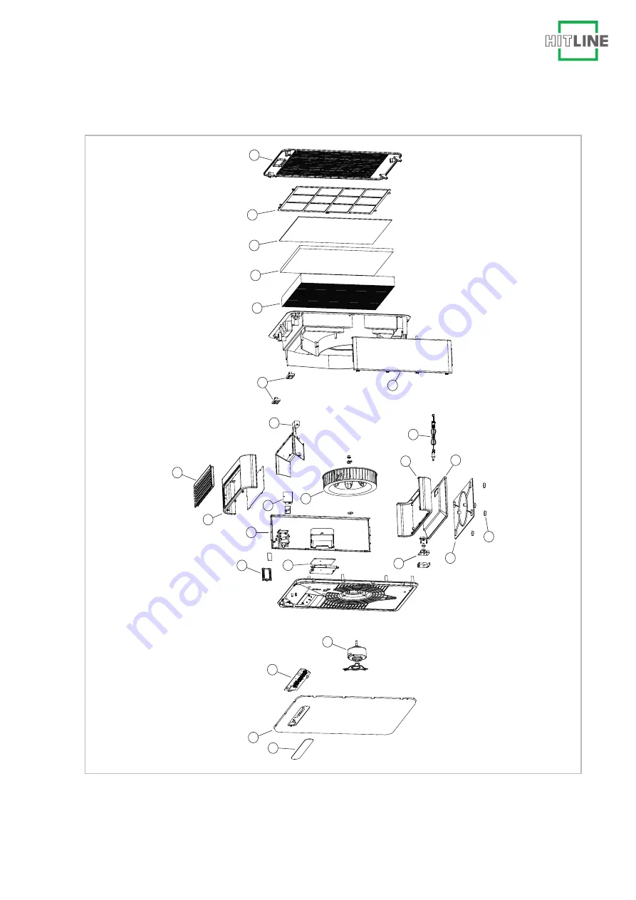
View of the unit
2
1
3
4
6
5
11
12
19
20
7
16
13
17
14
15
18
21
22
23
24
25
8
9
Fig. 18: Exploded view LRM 350, LRM 500
REMKO
Page 1: ...Operating and installation instructions REMKO Read the instructions prior to performing any task REMKO LRM series LRM 350 LRM 500 Air purifier 0276 2020 11 Edition 1 en_GB...
Page 2: ...rating instructions carefully before commis sioning using this device These instructions are an integral part of the system and must always be kept near or on the device Subject to modifications No li...
Page 3: ...uthorised modification and changes 5 1 9 Intended use 6 1 10 Warranty 6 1 11 Transport and packaging 6 1 12 Environmental protection and recycling 6 2 Technical data 7 2 1 Unit data 7 2 2 Unit dimensi...
Page 4: ...be fatal or cause serious injury WARNING This combination of symbol and signal word warns of a potentially hazardous situation which if not avoided may be fatal or cause serious injury CAUTION This co...
Page 5: ...ocal use DANGER Work on the electrical equipment must only be conducted by an authorised specialist 1 7 Safety notes for installation maintenance and inspection work n Appropriate hazard prevention me...
Page 6: ...partner in the first instance 1 11 Transport and packaging The devices are supplied in a sturdy shipping con tainer Please check the equipment immediately upon delivery and note any damage or missing...
Page 7: ...tage Sleep 1 2 3 Room area application area per stage m2 15 20 20 28 28 35 Air flow volume per stage setting m3 h 101 150 210 325 Power consumption per stage W 5 8 11 40 Max current consumption A 0 04...
Page 8: ...area application area per stage m2 20 30 30 40 40 50 Air flow volume per stage setting m3 h 130 210 290 457 Power consumption per stage W 5 8 14 57 Max current consumption A 0 04 0 07 0 15 0 36 Sound...
Page 9: ...g 1 Unit dimensions LRM 350 all measurements in mm LRM 500 682 190 440 4 3 2 1 3 2 1 8h 4h 2h REMKO Fig 2 Unit dimensions LRM 500 all measurements in mm We reserve the right to modify the dimensions a...
Page 10: ...in humans and the environment The following physical effects enable these foreign substances to be filtered out of the room air Sieve effect Particles that are larger than the free space between the...
Page 11: ...ers Fig 7 Electrostatic charging 3 2 Unit description The units have been designed for universal and straightforward air purification Their compact dimensions allow the unit to be transported and set...
Page 12: ...downstream filters from excessive loading and premature satu ration by larger particles Particles of medium size such as coarse dust and fine sand stick to their surface due to their inertia and the d...
Page 13: ...leep night mode key Pressing this key activates and deactivates night mode When night mode is activated the fan speed is reduced to a minimum and the control panel lighting is dimmed 6 AQ air quality...
Page 14: ...ot yet announce the change To do this press and hold the filter key for 3 seconds when the unit is switched off As soon as the LEDs start flashing the desired filter can be selected by pressing the ke...
Page 15: ...closed to the neighbouring atmosphere n The output of the unit is dependent on the con ditions inside the room room temperature rel ative humidity and particle emissions n No emission sources should b...
Page 16: ...fier to the mains the unit should be switched off not oper ating The operating unit emits an acoustic signal 2 Actuate the ON OFF key The operating unit emits an acoustic signal The ON OFF button ligh...
Page 17: ...ivated carbon granulate cassette HEPA filter General information on care and maintenance DANGER Care and maintenance work may only be car ried out if the unit is disconnected from elec trical power n...
Page 18: ...ro strips off the activated carbon granulate cas sette 4 Pull the granular activated carbon cartridge out of the unit by the tab 5 Pull the HEPA filter out of the unit by the tab To insert the filters...
Page 19: ...with new original filters Handle used filters with care and dispose of them as soon as possible to prevent particles from separating from the filter media and getting back into the room air If the us...
Page 20: ...Malfunction Possible causes Remedial measures The unit does not start or switches itself off Power failure Check the voltage and if neces sary wait for it to come back on Defective mains fuse Arrange...
Page 21: ...10 View of the unit 2 1 3 4 6 5 10 11 12 19 20 7 16 13 17 14 15 18 21 22 23 24 25 8 9 Fig 18 Exploded view LRM 350 LRM 500 REMKO 21...
Page 22: ...ousing side left 8 Housing top section 9 Air outlet finned grille 10 Air quality sensor 11 Fan wheel 12 Housing cover microswitch 13 Housing floor 14 Base plate 15 Rubber foot 16 Pedestal 17 Power plu...
Page 23: ...s 4 General 4 Identification of notes 4 Note for inspection work 5 Note for installation work 5 Note for maintenance work 5 Notes for the operator 5 Personnel qualifications 4 Safety conscious working...
Page 24: ...5232 606 260 E mail info remko de URL www remko de REMKO GmbH Co KG Klima und W rmetechnik Im Seelenkamp 12 32791 Lage Hotline within Germany 49 0 5232 606 0 Hotline International 49 0 5232 606 130 W...