


9
Faults Fx
The control PCB mounted in the
units differentiates between 6
different faults:
F1 - Fault at the flame monitoring
unit from loss of the flame.
F2 - Tripping of the safety
thermostat.
F3 - Malfunction by the burner
motor.
F4 - Malfunction by one of the
NTC sensors.
F6 - Malfunction of the
control
PCB.
F8 - Flame monitoring sensor
defect.
The faults F1 and F2 are caused by
safety devices and therefore are
permanent:
The fault persists when switching
off and restarting the mains
connection and can only be
unlocked manually.
The faults F3, F6 and F8 must be
unlocked manually by switching
off and restarting the mains
connection.
The fault F4, on the other hand,
resets itself: after remedy of the
cause of fault, the fault report
ceases.
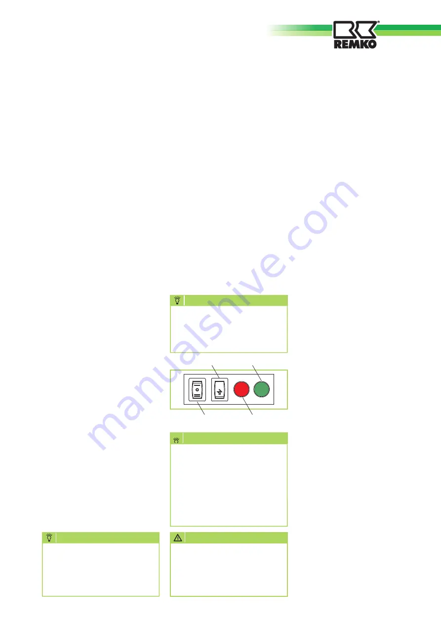
Reset button
On the front of the unit a
manually-actuated reset button
is installed, which enables the
unlocking of the unit after the
faults F1, F2, F3 or F8 in the
case of the lack of electronic
temperature regulation.
Summer/Winter toggle
Also on the front of the unit, a
manually-operated toggle switch
I / 0 / II is installed, which enables
switching the unit from winter
operation [I] to summer operation
[II] with only ventilation, in
case the electronic temperature
regulation is not present.
Air/gas premix
The units are equipped with a
burner with complete air/gas
premix.
This mixing process takes place in
the fan of the burner motor.
The air suctioned in by the fan
flows through the Ventura tube,
where an underpressure is created,
which draws in the gas.
In the process, a constant air/gas
mixture is created.
The ratio of air and gas pressure is
01:01.
This value can be changed through
the offset regulating screw found
on the gas valve.
The amount of gas is already
adjusted upon delivery of the units
and the screw is sealed.
With the adjusting screw located at
the Venturi tube, a fine adjustment
can take place, which regulates
the maximum gas flow rate and
thus determines the carbon dioxide
(CO
2
) content of the exhaust
The screw is not sealed in order
to enable conversion of the fan-
assisted air heater to another type
of gas.
PLEASE NOTE:
For the offset and CO
2
adjustment.
The control PCB of the units
enables the speed regulation of the
burner motor with DC depending
on the heat output required in the
space.
By changing the speed the air flow
rate and thus the gas flow rate are
changed.
Minimum and maximum speeds of
the fan are two values that cannot
be changed.
The procedure for unlocking
the permanent faults F1 and
F2 is described in the chapter
for the user.
NOTE
With electronic temperature
regulation the toggle switch
must always be switched to
position [I] winter operation.
NOTE
Without electronic
temperature regulation,
swapping both the reset
button and the toggle switch
through the terminal block
M1 inside the burner cabinet
in the installation location is
recommended.
NOTE
ATTENTION
All unit parameters can only
be changed in combination
with the electronic
temperature regulation
ATR-6.
[II]Summer/ 0 / [I] winter
toggle switch
Reset button
GREEN LED
RED LED


