44
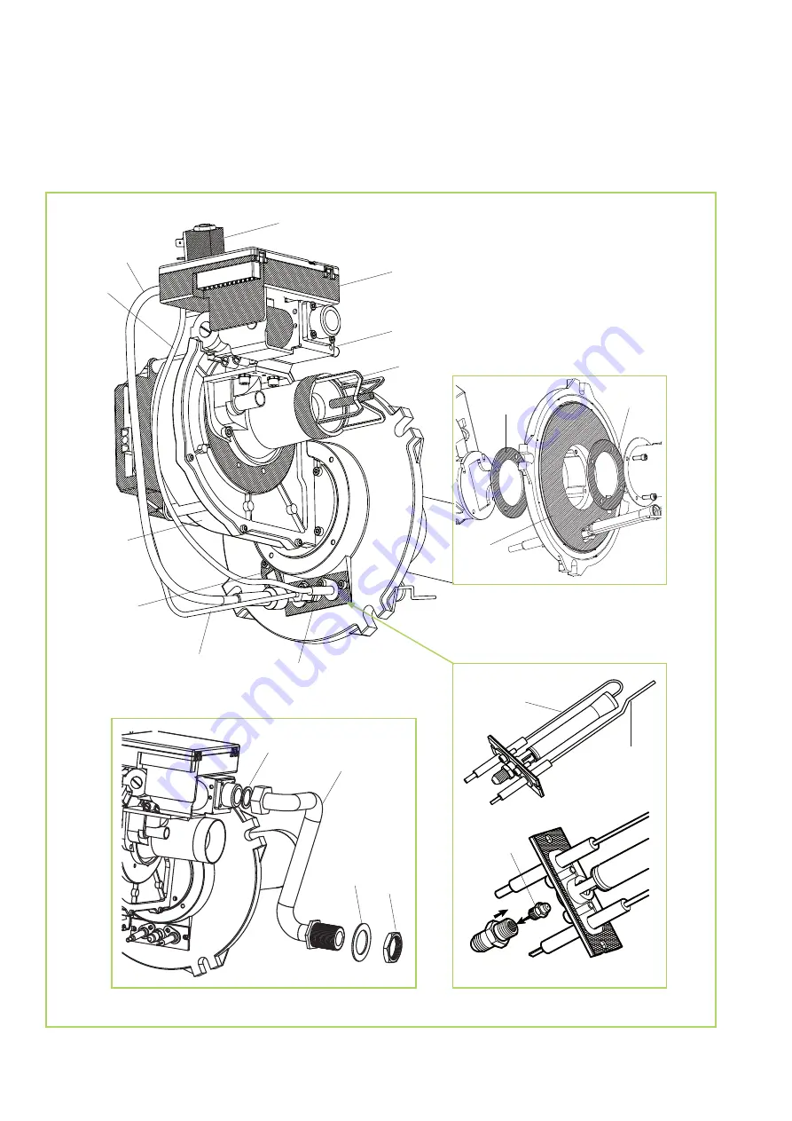
REMKO GPM
16
21
22
18
19
25
29
28
27
31
32
33
34
24
15
23
20
26
30
17
Venturi burner
We reserve the right to modify the dimensions and constructional design as part of the ongoing technical development process.
Page 1: ...Issue D U10 REMKO GPM Gas Wall Heater Operation Technology Spare parts...
Page 2: ......
Page 3: ...rs or misprints Safety notes 4 Unit layout 5 Description of the unit 6 Instructions for the user 12 Intended use 21 Customer service and warranty 21 Environmental protection and recycling 21 Instructi...
Page 4: ...he mounting of the units may only be executed at the points provided for this purpose at the factory The units may not be installed or operated in potentially flammable or explosive environments The u...
Page 5: ...apacity must be checked reinforcements must be installed when necessary Brackets must be securely anchored to the wall or ceiling and the units must be attached to the brackets at the points provided...
Page 6: ...l lines as well as the plug connection for the mains connection In the right hand side section the necessary components for the control and safety are found behind the inspection door including the el...
Page 7: ...ulation the burner is only started if the contact 7 9 of the terminal block M1 is closed At the beginning while igniting the control PCB starts the fan of the burners so that the combustion chamber is...
Page 8: ...here is a safety thermostat STB with automatic deactivation and positive security a release of the sensitive element triggers a safety shutdown The thermostat is installed in the area of the heat exch...
Page 9: ...through the Ventura tube where an underpressure is created which draws in the gas In the process a constant air gas mixture is created The ratio of air and gas pressure is 01 01 This value can be chan...
Page 10: ...he unit so that the intake temperature of the fans is monitored The modulation takes place according to the value measured by this sensor in relationship to the pre adjusted value on the microprocesso...
Page 11: ...n of layers and at the same time reduce heat loss in the room s air The units are delivered with the following factory settings Modulation temperature REG SAN 24 C Neutral correction range A24 2 C Cor...
Page 12: ...of the two operating modes the units can be used for both heating or air circulation on warmer days To switch on the winter phase the toggle switch only needs to be set to the winter symbol To switch...
Page 13: ...t regulation of the unit corresponding to the heat requirement Operation display Display of faults and malfunctions Reset button Operation without batteries Two wire connection without polarity F4 Sen...
Page 14: ...as sharp objects should be avoided With interruption of voltage supply for more than 5 hours the stored values in the operating unit are lost ATTENTION A reset may only be executed 20 seconds after t...
Page 15: ...and hold KM for approx 8 10 seconds until the following appears on the display INFO REG ERR K1 K2 K3 K4 Press K4 and then K1 LANG Select the desired language with the keys K and K Press K4 OK for con...
Page 16: ...menu mode heating ON returns to the display of the operating menu The value of the desired room temperature can be changed with the keys K or K in this status whereby it can be selected within the pr...
Page 17: ...ective temperatures are now adjusted for the selected day The four different parameters T1 T2 and T3 are shown during the programming as follows Dash below flashes T1 two balls flash alternately T2 on...
Page 18: ...INFO REG ERR K1 K2 K3 K4 Press K4 and change to the following page where the following appears LANG PAR PARK K1 K2 K3 K4 Press K3 PARK in order to arrive at the TSP parameters The display shows PARAM...
Page 19: ...erature regulation must first be set to 1 For adjustment of the ventilation function the SAN value must then be set to the respective operation mode In doing so proceed as follows Press KM and page 1...
Page 20: ...ic settings with heating switched on the times set for this operation cannot be displayed during the ventilation phase NOTE NOTE In both automatic and manual operation the symbol of a water tap appear...
Page 21: ...or contractual partner Intended use Disposal of packaging With the disposal of the packaging material please consider our environment Our units were carefully packed for the transport and delivered in...
Page 22: ...in mm The height 2500 mm corresponds to the minimum height indicated for Hanging equipment by the guidelines Two different types of brackets are available for the installation as accessories Fixed an...
Page 23: ...n the bracket and nut Position the unit on the brackets so that the holes of the unit line up with those of the brackets whereby the corners of the brackets must be flush with the front edge of the un...
Page 24: ...on air supply must be planned and executed in observance of the respective local guidelines In addition installation on outside walls must be coordinated with the responsible district master sweep The...
Page 25: ...diameter After fastening the segment the pressure loss for the individual parts should be determined depending on the respective unit in use The pressure loss is different with each part because the f...
Page 26: ...openings in the walls of the room The dimensions and characteristics determined in the standards must be adhered to In particular DVGW TRGI 2008 Sec 5 2 2 and TRF Sec 7 2 2 should also be observed The...
Page 27: ...matic side view L1 L2 Installation height 2 5 3 5 m Schematic front view In this version the position of the connections to the unit must be changed meaning they must be repositioned from behind to ab...
Page 28: ...y be connected to the mains through outlets plugs with reverse polarity protection Electrical supply 230 1 50 Minimum cross section of the mains supply 1 5 mm NOTE Phase and neutral lines may absolute...
Page 29: ...gas supply should be executed with a suitable removable screw connection free of voltage and vibration The components described in the applicable gas guidelines as well as the locally required compon...
Page 30: ...nspections of all gas conveying connections must be conducted ATTENTION ATTENTION Gas lines may never be used for the grounding of electrical equipment Commissioning It must be ensured that a gas supp...
Page 31: ...utton again and holding it for 2 3 seconds This mode is displayed through the continuous illumination of the green LED After completion of all steps for the initial commissioning the user is instructe...
Page 32: ...r CY MT I3B P G30 G31 30 mbar EE LT LV II2H3B P G20 20 mbar G30 G31 30 mbar IS I3P G31 37 mbar SK II2H3B P G20 20 mbar G30 G31 30 mbar SI II2H3B P G20 20 mbar G30 G31 30 mbar BG RO TR II2H3B P G20 20...
Page 33: ...thermostat s The inspection must be carried out in the unit heating mode Heat up the thermostat sensor with a hot air gun or other suitable means until the fault F2 is displayed Let the thermostat sen...
Page 34: ...ion of cleaning reinstall the cladding A of the flue gas collector bin and check for tightness After the work is completed switch on the unit again and conduct a test run Monitoring electrode Flame mo...
Page 35: ...witch on ON see figure below to the inside edge of the card This configuration is necessary in order to guarantee the proper function of the NTC1 sensor Bridge to NTC CR switch on ON Programming of th...
Page 36: ...n and holding it for 2 3 seconds This mode is displayed through the continuous illumination of the green LED This also happens if the power supply of the unit is switched off and then on again Unit wi...
Page 37: ...utput check 1 that the pressure at the input to the gas valve corresponds to the prescribed value for the respective gas type 2 that the CO2 content corresponds to the prescribed values for the gas ty...
Page 38: ...A34 10 10 95 REG SAN minimum value 10 A35 0 0 1 Summer operation of the fan 11 C1 0 0 1 Room correction 12 C3 60 0 255 Delay time of the fan ON 13 C4 120 0 255 Delay time of the fan OFF 14 C5 0 0 1 H...
Page 39: ...K2 K3 K4 The set point appears through the arrows above key K4 Adjust the desired temperature value with the keys and e g 18 C Then press key KM in order to return to the output menu Display of the v...
Page 40: ...ls von dem NTC1 gemessenem Wert eingestellt ist Erscheint dieses Symbol auf dem Display a Netzanschluss b Buskabelverbindung zwischenTemperaturregelung und Steuerplatine c Elektromagnetische St rungen...
Page 41: ...lt oder falsch angeschlossen Netzanschluss ohne korrekten Nullleiter Z ndelektrode defekt oder falsch eingebaut berwachungselektrode defekt oder falsch eingebaut berwachungselektrode lose verliert bei...
Page 42: ...de E I Summer winter toggle switch F1 Fuse 4A F2 Fuse 2 5A LR Fault lamp LV Operating lamp M1 Terminal block NTC Sensor NTC 1 SB Fault clearing button STB Safety thermostat resetting TR Transformer 23...
Page 43: ...43 When ordering spare parts please state the computerised part no unit number and type see identification plate Exploded view 36 6 5 4 1 3 2 9 12 14 13 7 8 11 35 38 42 41 10 40 37 39...
Page 44: ...KO GPM 16 21 22 18 19 25 29 28 27 31 32 33 34 24 15 23 20 26 30 17 Venturi burner We reserve the right to modify the dimensions and constructional design as part of the ongoing technical development p...
Page 45: ...1110471 22 Ionisation cable 1110472 1110472 1110472 1110472 1110472 23 Inspection glass with seal 1110473 1110473 1110473 1110473 1110473 24 Ignition gas burner 1110474 1110475 1110476 1110477 111047...
Page 46: ...1080 894 243 283 400 1 109 296 Series Horizontal discharge A F AV TV L GPM15 80 80 367 204 105 GPM25 80 80 367 204 105 GPM35 80 80 367 204 105 GPM55 80 80 457 204 105 GPM 75 100 100 511 204 130 Series...
Page 47: ...al gas H m3 h 1 32 1 75 2 12 2 80 2 54 3 68 4 23 6 14 6 14 8 25 Gas flow rate natural gas L m3 h 1 54 2 03 2 46 3 26 2 95 4 28 4 92 7 13 7 13 9 59 Gas flow rate liquid gas kg h 0 79 1 05 1 27 1 68 1 5...
Page 48: ...eld staff are more than just salesmen above all they must advise our clients in the areas of air conditioning and heating technology Customer service Our equipment works with precision and reliability...